Facet joint implant and procedure

a facet joint and implant technology, applied in the field of facet joint implants, can solve the problems of reducing the separation of opposing facet joints, affecting the biomechanics of those joints, and often painful faces of facet joints, so as to improve lubrication, reduce pain, and reduce the effect of elastic materials

Inactive Publication Date: 2007-05-24
ZIMMER SPINE INC
View PDF23 Cites 159 Cited by
  • Summary
  • Abstract
  • Description
  • Claims
  • Application Information

AI Technical Summary

Benefits of technology

[0012] This invention provides a number of advantages, including but not limited to the following. The synthetic elastic material employed in the practice of this invention provides a surface to enhance lubrication within the facet joint, which can reduce pain associated with degenerated facet joints. The elastic material is relatively inexpensive. The method introduces the elastic material into the facet joint in a relatively non-invasive procedure. The elastic material is advantageously benign, biocompatible, elastic, and pliable, and can be formed from synthetic polymers previously used in the human body. Thus, at least some of the polymers that can be used in the practice of this invention are advantageously commercially available. When a solid elastic material is introduced into the facet joint, the elastic material can be introduced as an at least partially dehydrated solid in a shape that conforms to the cavity within the facet joint. In this regard, the at least partially dehydrated solid becomes re-hydrated after being introduced into the facet joint. The elastic material can thus swell to a larger size than the incision or hole that the elastic material is introduced through, thereby preventing the swelled elastic material from undesirably becoming expelled from the facet joint. Beneficially, the elastic material can be readily removed if, for example, it is later desired to remove the facet joint if a spinal fusion procedure is performed.

Problems solved by technology

The facet joint can often become painful during the degenerative process in the spine.
Loss of disc height can reduce the separation of opposing facet joints and alters the biomechanics of those joints.
The cartilage of the joint may become compromised or destroyed resulting in bone on bone contact in the joint.
This may cause significant pain.

Method used


Image

  • Facet joint implant and procedure
  • Facet joint implant and procedure
  • Facet joint implant and procedure

Examples


Embodiment Construction

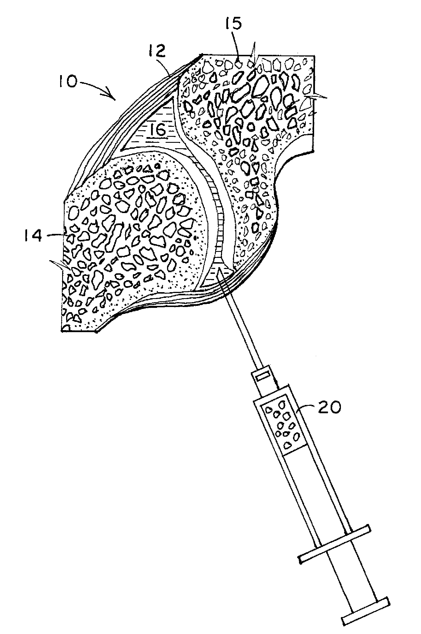
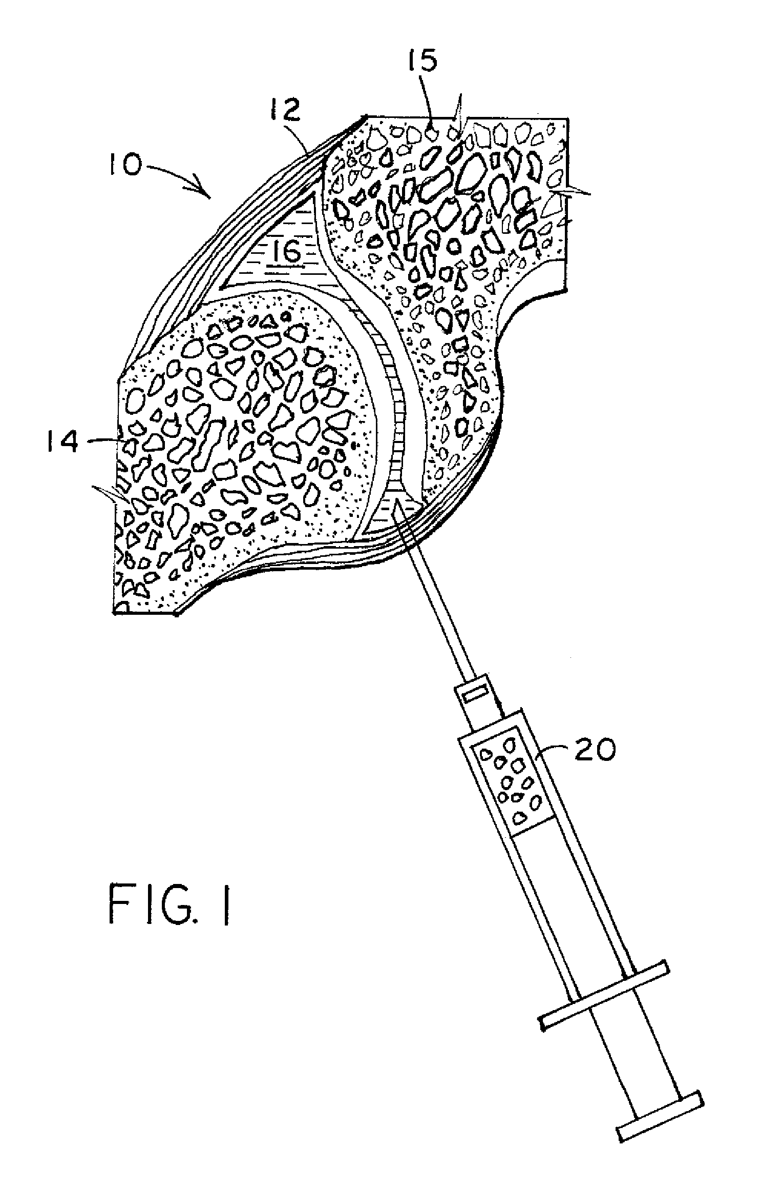
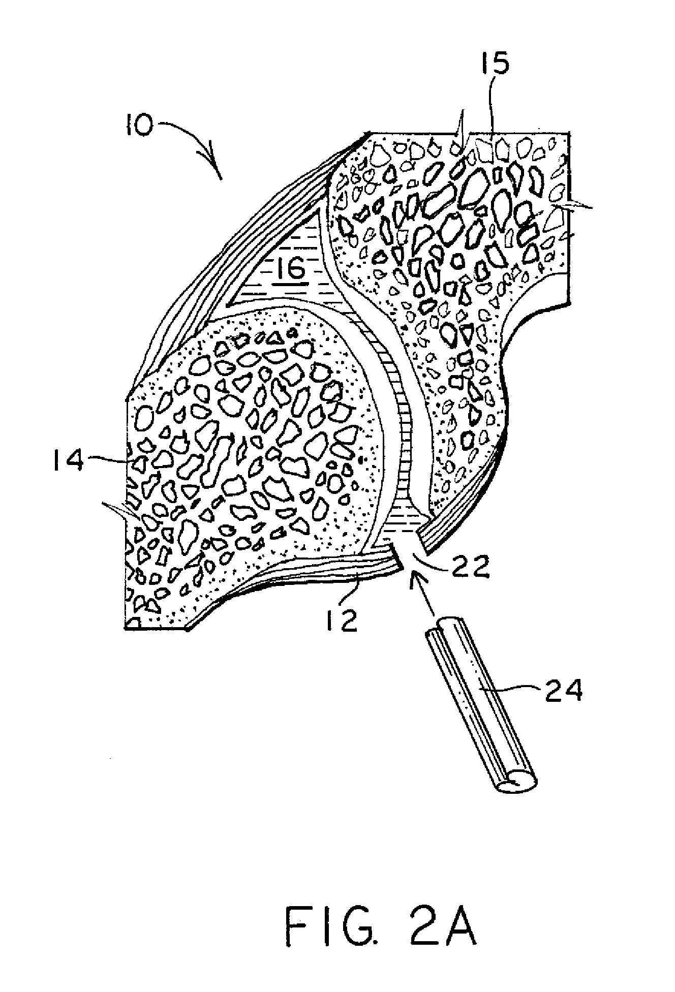
[0018]FIG. 1 illustrates a cross-section of a facet joint 10. The facet joint 10 includes the joint capsule 12 that attaches to the bone 14, 15 of an upper and lower vertebra. The joint capsule 12 and bones 14, 15 together define an inner cavity 16 that normally holds synovial fluid. Thus, the joint capsule 12 surrounds the inner cavity on the perimeter, and the bones 14, 15 define the upper and lower ends of the inner cavity 16. The synovial fluid provides lubrication for the facet joint. If the facet joint degenerates, there can be a lessoning of synovial fluid, reduction in space between the bones 14, 15 such that painful bone-on-bone contact occurs. The present invention provides a synthetic elastic material of appropriate shape and size to be placed in the cavity 16 so that bone-on-bone contact is reduced or eliminated, thereby reducing or eliminating pain for a patient. The implant may also provide lubrication for the facet joint.

[0019] After it is determined that a facet joi...


PUM

PropertyMeasurementUnit
areaaaaaaaaaaa
thicknessaaaaaaaaaa
thicknessaaaaaaaaaa

Abstract

A method for repairing a facet joint of a human vertebra having a joint capsule surrounding the facet joint. In the method, a synthetic elastic material is introduced into the facet joint. The synthetic elastic material can be a solid, swellable polymer that expands when hydrated upon being placed in the facet joint. The invention includes the implant and the method of making the implant.

Description

BACKGROUND OF THE INVENTION [0001] This invention relates to a facet joint implant and a method for distracting a facet joint and maintaining separation of the facet joint. [0002] The facet joints, knees, and elbows are sometimes referred to as synovial joints. A synovial joint allows movement between two bones. In a synovial joint, the ends of the bones are covered with a material called articular cartilage. This material is a slick spongy material that allows the bones to glide against one another without much friction. [0003] Surrounding the facet joint is a watertight sack made of soft tissue and ligaments. This sack creates what is called the “joint capsule”. The ligaments are soft tissue structures that hold the two sides of the facet joint together. The ligaments around the facet joint combine with the synovium to form the joint capsule that is filled with fluid (synovial fluid). This fluid lubricates the joint to decrease the friction. [0004] The facet joint can often become...

Claims


Application Information

Patent Timeline
Patent Type & Authority Applications(United States)
IPC IPC(8): A61F2/28
CPCA61B17/562A61F2/38A61F2/4405A61F2/441A61F2002/30075A61F2002/30242A61F2002/30291A61F2002/30677A61F2210/0061A61F2230/0071A61F2230/0091
Inventor HOOPER, DAVID
Owner ZIMMER SPINE INC
Why Eureka
Try Eureka