

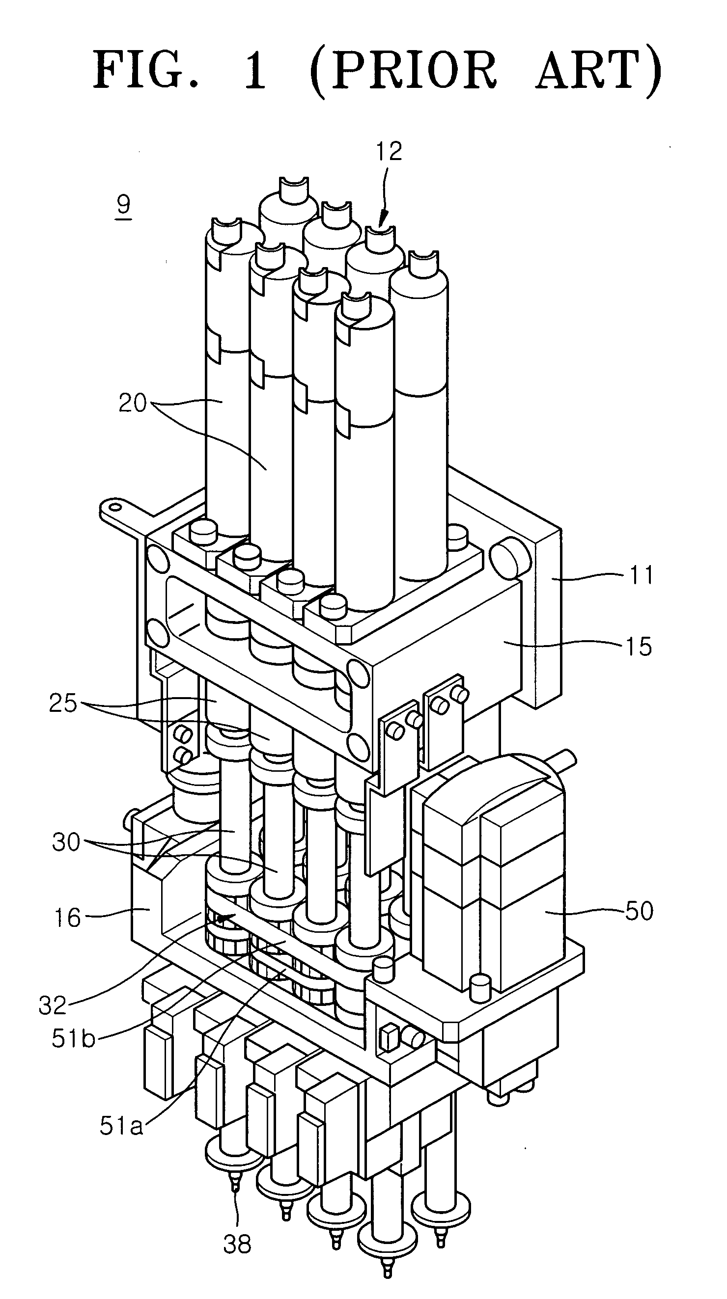
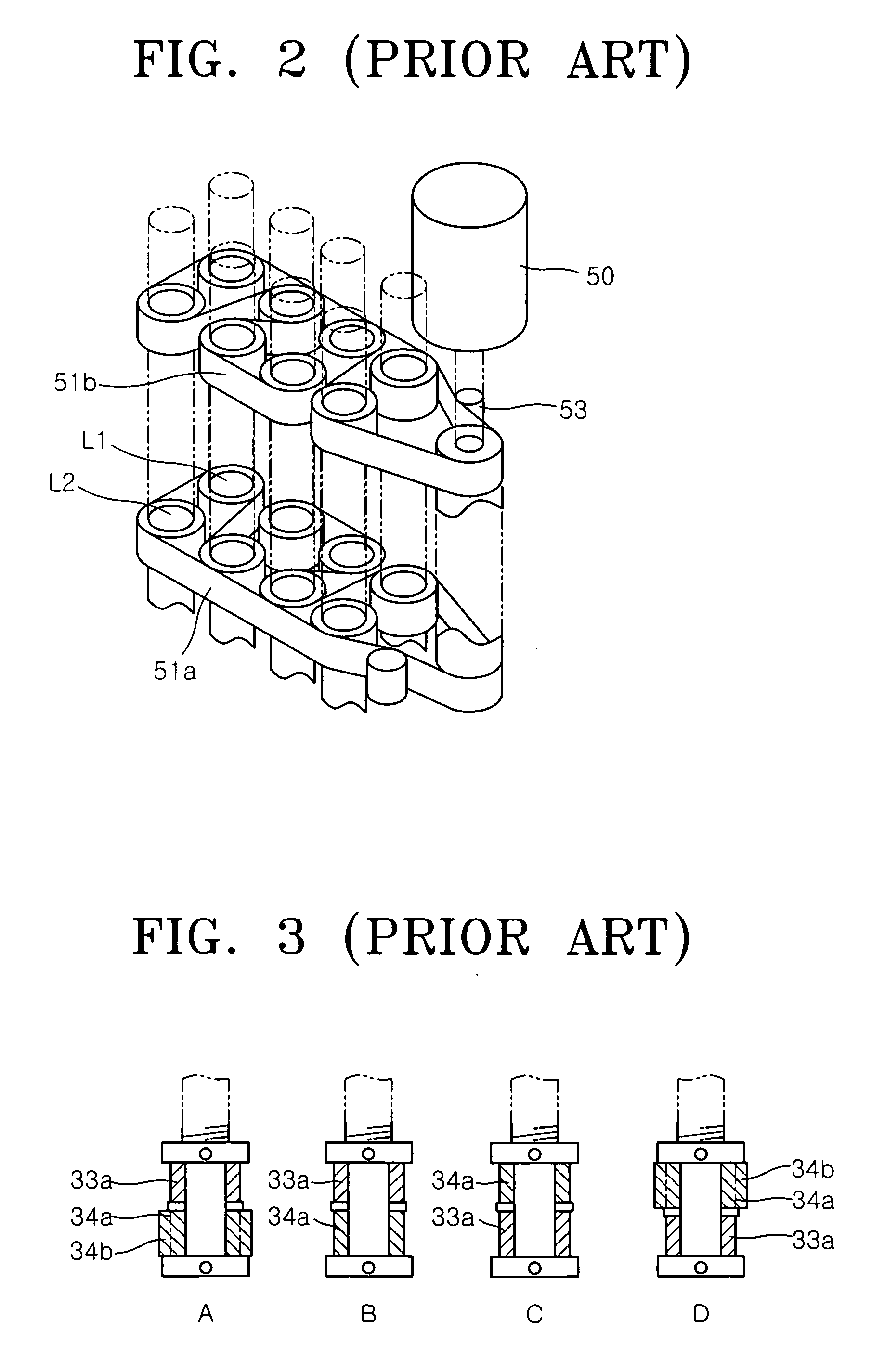
Head assembly for chip mounter
a technology of mounting brackets and head assemblies, which is applied in the direction of manufacturing tools, yarn, drafting machines, etc., can solve the problems of high-precision mounting, high manufacturing cost and price of electronic components, and the head assembly b>9/b> becomes bulky, so as to achieve low manufacturing cost, no backlash, and high-speed movement
- Summary
- Abstract
- Description
- Claims
- Application Information
AI Technical Summary
Benefits of technology
Problems solved by technology
Method used
Image

Examples
Embodiment Construction
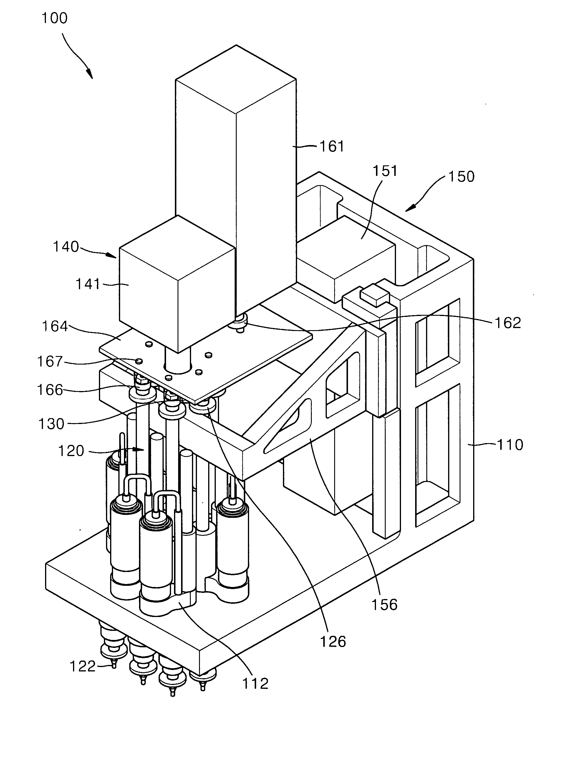
[0040]FIG. 4 is a perspective view of a head assembly 100 for a chip mounter according to a first embodiment of the present invention and FIG. 5 illustrates an elevating driver and a horizontal driver shown in FIG. 4. Referring to FIGS. 4 and 5, the head assembly 100 includes a housing 110, a plurality of nozzle spindles 120, a selection member 130, a horizontal driver 140, and an elevating driver 150. The housing 110 has a plurality of spindle receiving holes 112.
[0041] Each nozzle spindle 120 of the plurality is fitted with a nozzle 122 configured to pick up and mount electronic components. Each nozzle spindle 120 of the plurality is movably and rotatably inserted into a corresponding spindle receiving hole 112. Bearings (not shown) may be interposed between the nozzle spindles 120 and the spindle receiving holes 112 in order to support vertical motion and rotational motion of the nozzle spindles 120.
[0042] The selection member 130 is configured to select one or more of the nozz...
PUM
| Property | Measurement | Unit |
|---|---|---|
| angle | aaaaa | aaaaa |
| circumference | aaaaa | aaaaa |
| distance | aaaaa | aaaaa |
Abstract
Description
Claims
Application Information