Fuel vapor storage canister

a technology of fuel vapor and canisters, which is applied in the direction of machines/engines, combustion air/fuel air treatment, separation processes, etc., can solve the problems of increasing the length and volume of the gas passage in the adsorption layer, the inability to reduce or cancel the temperature change during the fuel vapor adsorption and desorption, and the increase of the cross-sectional area and the length of the gas passage. , to achieve the effect of reducing the purging efficiency

Inactive Publication Date: 2007-05-31
MAHLE FILTER SYST JAPAN CORP
View PDF7 Cites 37 Cited by
  • Summary
  • Abstract
  • Description
  • Claims
  • Application Information

AI Technical Summary

Benefits of technology

[0006] Since adsorption and desorption of fuel vapor to the adsorbent are carried respectively on exothermic and endothermic reactions accompanying a temperature change, it is required to suppress a temperature rise during the adsorption and a temperature lowering during the desorption in order to maintain good adsorbing and desorbing performances of the adsorbent. However, in the above-discussed conventional canister, there is a tendency that the cross-sectional area, length and volume of the gas passage increase in the adsorption layer particularly on the side of the charge and purge ports or upstream side. Accordingly, heat from the outside is difficult to be transmitted to an inner or deep section of the adsorption layer, and therefore heat tends to stay at the inner section of the adsorption layer. Thus, there arises a problem that a temperature change during the fuel vapor adsorption and desorption cannot be reduced or cancelled. Additionally, if the cross-sectional area and length of the adsorption layer increases, the purge gas is difficult to flow to the outer peripheral section of the gas passage on a cross-sectional plane perpendicular to the axis of the gas passage, thereby ununiformizing the flow of gas in the gas passage throughout the cross-sectional plane. This will lower the purging efficiency of the canister.

Problems solved by technology

However, in the above-discussed conventional canister, there is a tendency that the cross-sectional area, length and volume of the gas passage increase in the adsorption layer particularly on the side of the charge and purge ports or upstream side.
Accordingly, heat from the outside is difficult to be transmitted to an inner or deep section of the adsorption layer, and therefore heat tends to stay at the inner section of the adsorption layer.
Thus, there arises a problem that a temperature change during the fuel vapor adsorption and desorption cannot be reduced or cancelled.
Additionally, if the cross-sectional area and length of the adsorption layer increases, the purge gas is difficult to flow to the outer peripheral section of the gas passage on a cross-sectional plane perpendicular to the axis of the gas passage, thereby ununiformizing the flow of gas in the gas passage throughout the cross-sectional plane.
This will lower the purging efficiency of the canister.

Method used


Image

  • Fuel vapor storage canister
  • Fuel vapor storage canister
  • Fuel vapor storage canister

Examples


Embodiment Construction

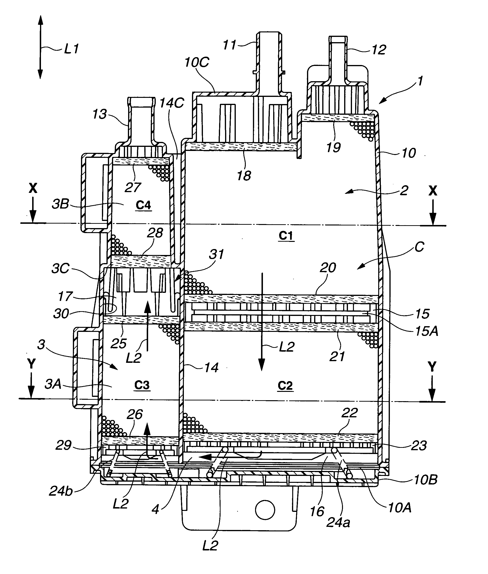
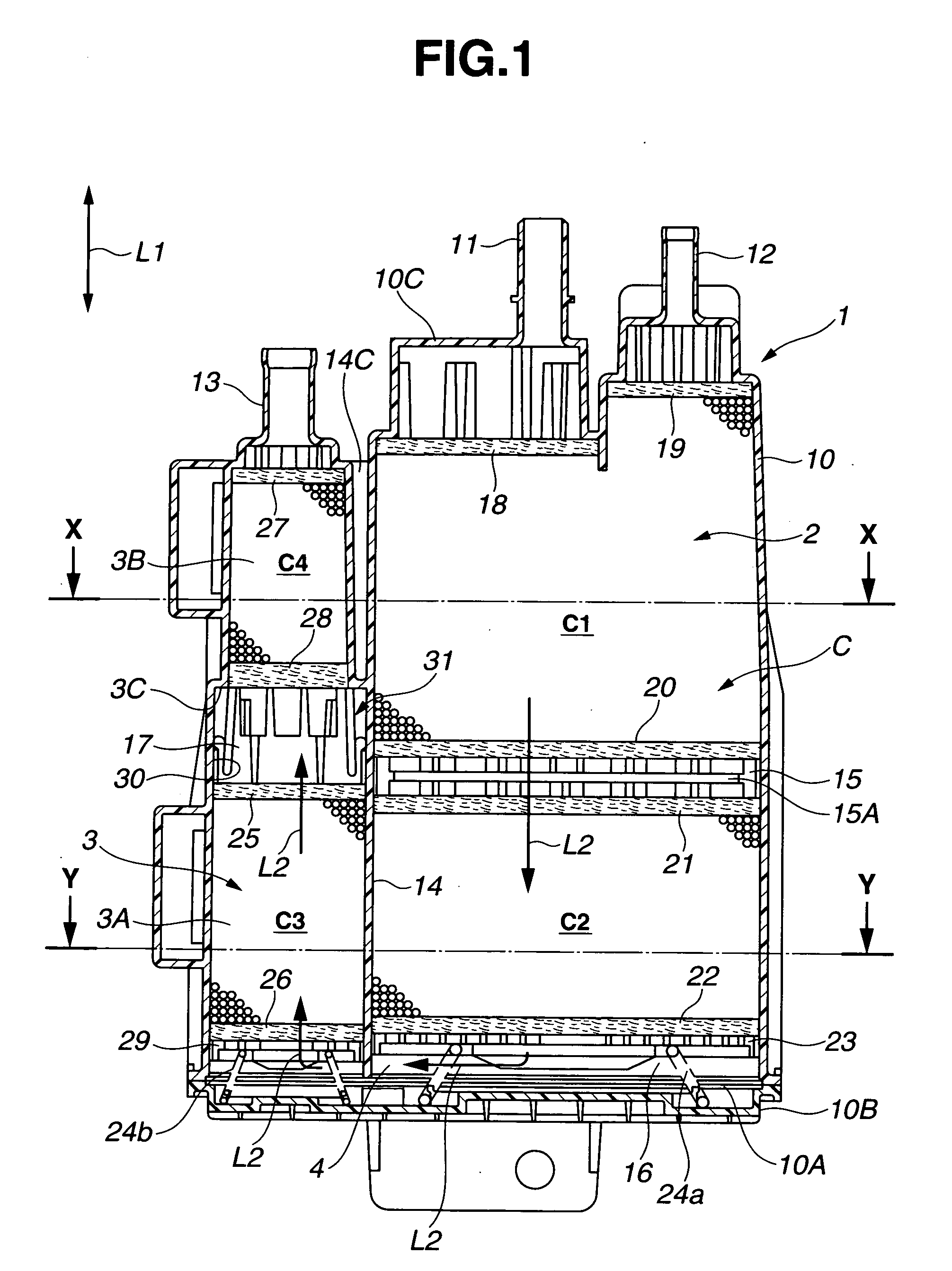
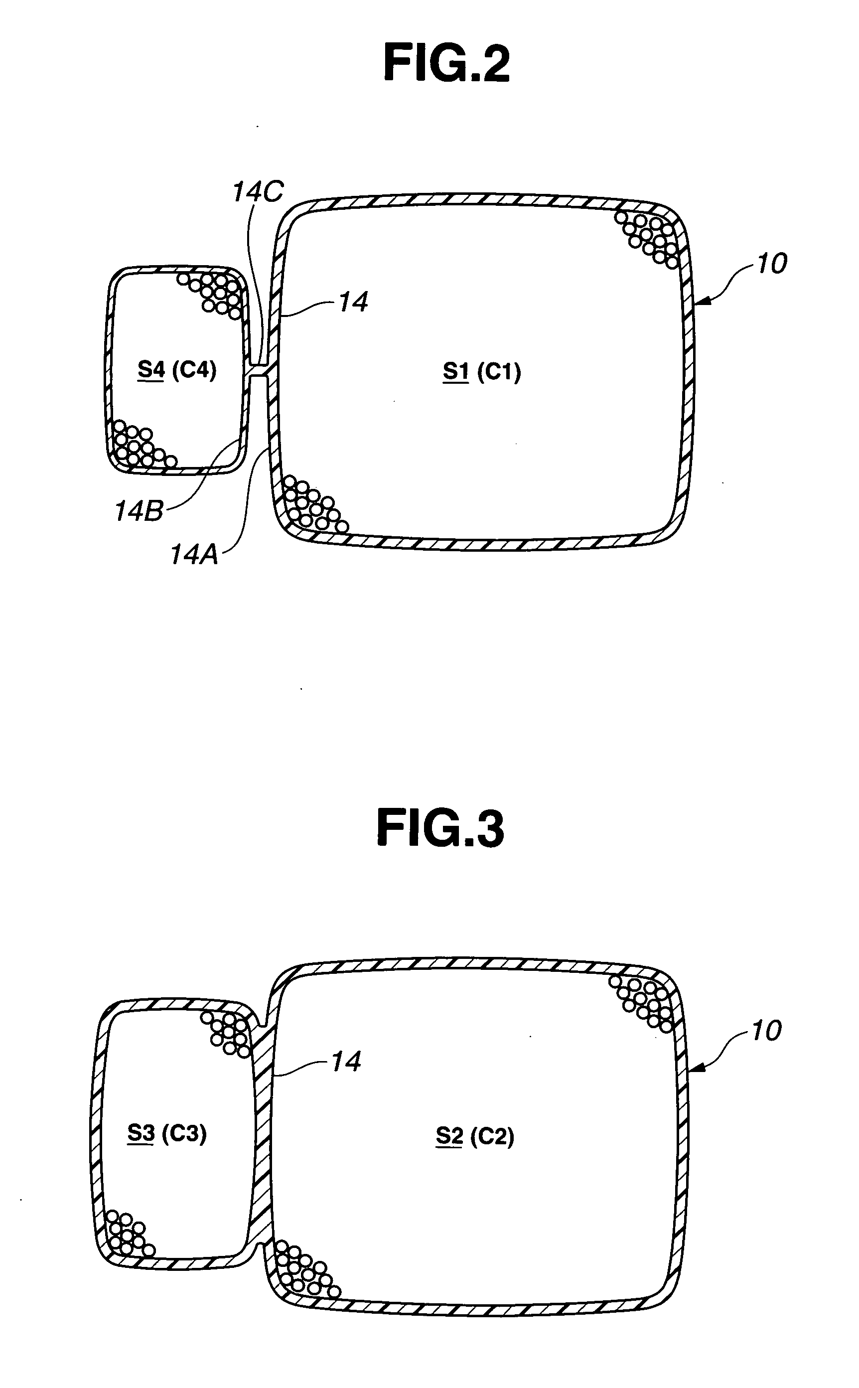
[0015] Referring now to FIGS. 1, 2 and 3 of the drawings, an embodiment of a fuel vapor storage canister according to the present invention is illustrated. The canister comprises a casing 1 as a main body, formed of a resin material or plastic. The casing 1 includes a generally cup-shaped casing main body 10, and a plate-shaped bottom lid section 10B which is joined and fixed to the end face of an open end section 10A of the casing main body 10 in such a manner as to close the open end section 10A formed opening at one end in a longitudinal or vertical direction L1 of the casing 1 (i.e., a vertical direction in FIG. 1, or a direction in which a port wall section 10C discussed after and the bottom lid section 10B face each other). The casing main body 10 has the port wall section 10C which is opposite to the open end section 10A. The port wall section 10C is formed with a charge port 11 which is connected to a fuel tank through a piping (not shown), a purge port 12 which is connected...


PUM


Abstract

A fuel vapor storage canister for an automotive vehicle, includes a casing formed thereinside with charge, purge and drain ports connected to a gas passage. First, second, third and fourth adsorption layers are disposed in the gas passage and arranged in order of first, second, third and forth adsorption layers from side of the charge port along a longitudinal direction of the gas passage. Each adsorption layer includes a fuel vapor adsorbent. Additionally, a first space section is formed between the first and second adsorption layers. A second space section is formed between the second and third adsorption sections. A third space section is formed between the third and fourth adsorption sections. Each space section has a width in the longitudinal direction of the gas passage.

Description

BACKGROUND OF THE INVENTION [0001] This invention relates to improvements in a fuel vapor storage canister as a fuel vapor treatment device for treating fuel vapor generated, for example, from a fuel tank of an automotive vehicle. [0002] Hitherto a fuel vapor storage canister as a fuel vapor treatment device has been generally used in order to suppress release of fuel vapor generated within a fuel tank to atmospheric air in a gasoline-fueled automotive vehicle, as disclosed in Japanese Patent Provisional Publication No. 2005-23835. This canister includes a casing formed thereinside a gas passage which is filled with a fuel vapor adsorbent such as activated carbon. Charge and purge ports for fuel vapor are provided at one end of the gas passage, while a drain port for fuel vapor is provided at the other end of the gas passage. During stopping of the vehicle, fuel vapor generated from the fuel tank is introduced into the canister and adsorbed by the adsorbent. During operation of an e...

Claims


Application Information

Patent Timeline
Patent Type & Authority Applications(United States)
IPC IPC(8): B01D59/26F02M25/08
CPCB60K15/03504B60K2015/03514F02M25/0854
Inventor YAMADA, EIJINAKANO, MASARUUCHINO, MASASHIOSAKI, TAKAHIRO
Owner MAHLE FILTER SYST JAPAN CORP
Why Eureka
Try Eureka