

Apparatus and process for plasma-enhanced atomic layer deposition
a technology of atomic layer deposition and apparatus, which is applied in the direction of chemical vapor deposition coating, solid-state devices, coatings, etc., can solve the problems of many limitations of pe-ald processes, slow deposition rate of processes, and inability to meet the requirements of production
- Summary
- Abstract
- Description
- Claims
- Application Information
AI Technical Summary
Benefits of technology
Problems solved by technology
Method used
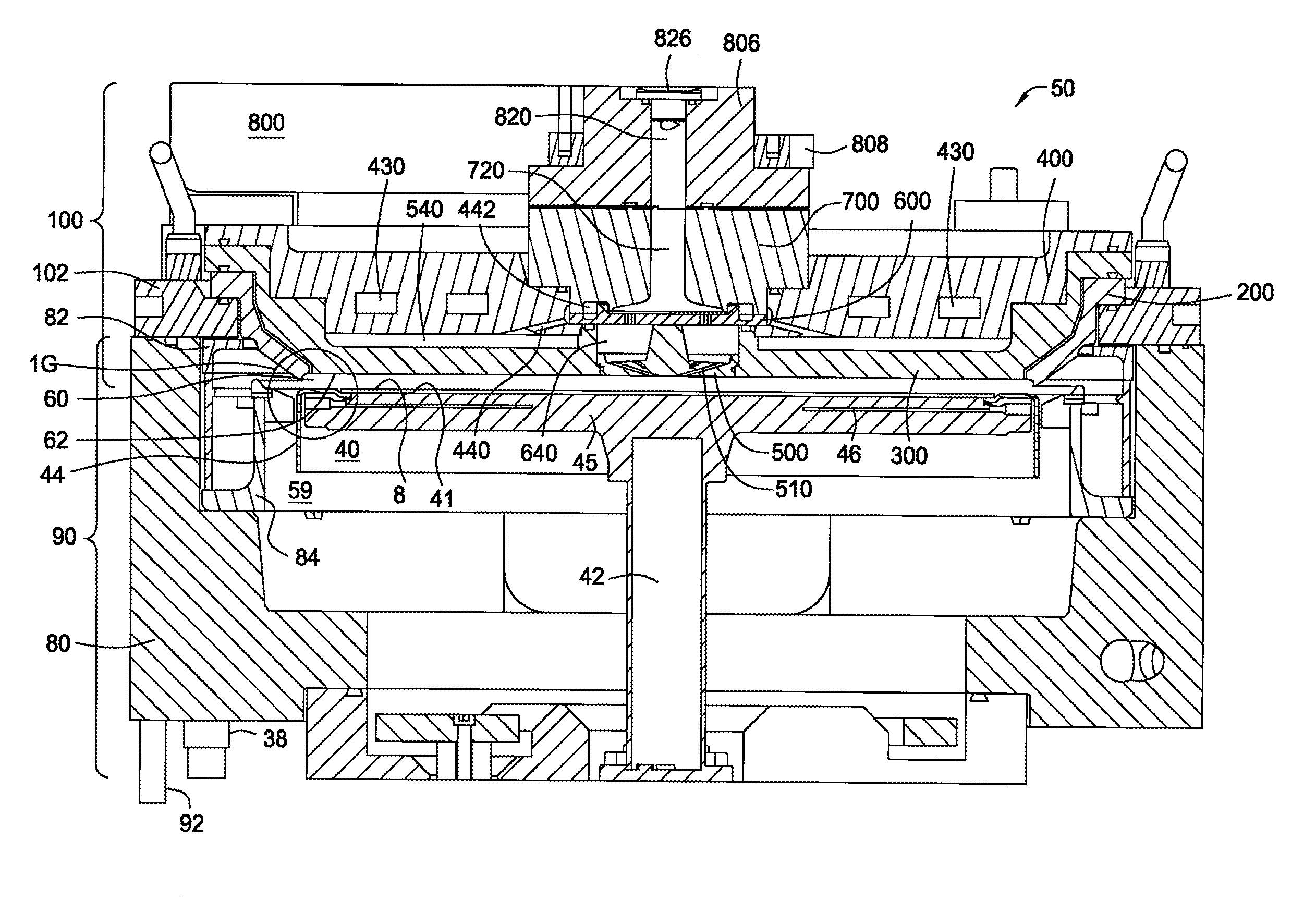
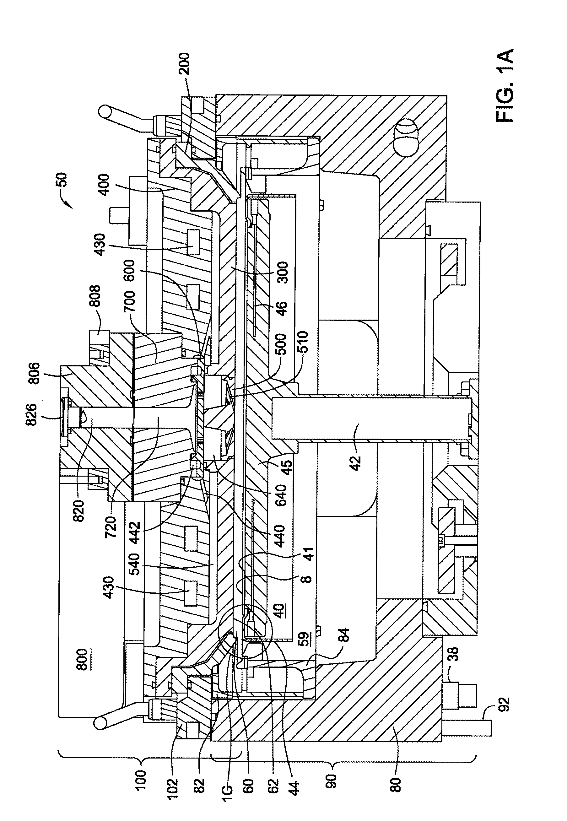
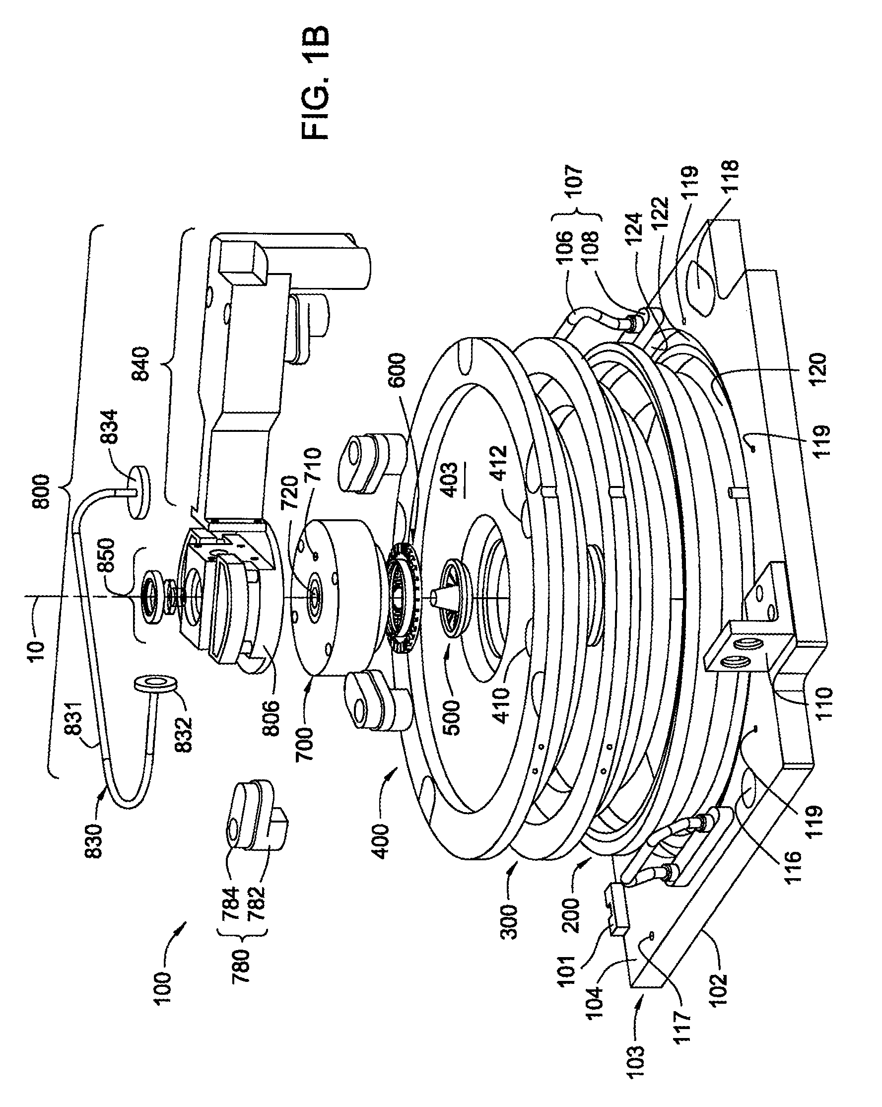
Image

Examples
experiment 1
(DMPD)2Ru with Constant Flow of NH3 and Intermediate Plasma
[0178] The ruthenium precursor used during this experiment was bis(2,4-dimethylpentadienyl)ruthenium ((DMPD)2Ru). During the experiment, the pressure within the process chamber was maintained at about 2 Torr and the substrate was heated to about 300° C. An ALD cycle included the following steps. A ruthenium precursor gas was formed by passing a nitrogen carrier gas with a flow rate of about 500 sccm through an ampoule of (DMPD)2Ru heated at a temperature of about 80° C. The substrate was exposed to the ruthenium precursor gas with a flow rate of about 500 sccm and ammonia gas with a flow rate of about 1,500 sccm for about 3 seconds. The flow of the ruthenium precursor gas was stopped while the flow of the ammonia gas was maintained during a purge step. The purge step was conducted for about 2 seconds. Subsequently, a plasma was ignited to form an ammonia plasma from the ammonia gas while maintaining the flow rate. The RF ge...
experiment 2
(MeCp)(EtCp)Ru with Constant Flow of NH3 and Intermediate Plasma
[0179] The ruthenium precursor used during this experiment was methylcyclopentadienyl ethylcyclopentadienyl ruthenium ((MeCp)(EtCp)Ru). During the experiment, the pressure within the process chamber was maintained at about 2 Torr and the substrate was heated to about 300° C. An ALD cycle included the following steps. A ruthenium precursor gas was formed by passing a nitrogen carrier gas with a flow rate of about 500 sccm through an ampoule of (MeCp)(EtCp)Ru heated at a temperature of about 80° C. The substrate was exposed to the ruthenium precursor gas with a flow rate of about 500 sccm and ammonia gas with a flow rate of about 1,500 sccm for about 3 seconds. The flow of the ruthenium precursor gas was stopped while the flow of the ammonia gas was maintained during a purge step. The purge step was conducted for about 2 seconds. Subsequently, a plasma was ignited to form an ammonia plasma from the ammonia gas while main...
experiment 3
(MeCp)(Pv)Ru with Constant Flow of NH3 and Intermediate Plasma
[0180] The ruthenium precursor used during this experiment was methylcyclopentadienyl pyrrolyl ruthenium ((MeCp)(Py)Ru). During the experiment, the pressure within the process chamber was maintained at about 2 Torr and the substrate was heated to about 300° C. An ALD cycle included the following steps. A ruthenium precursor gas was formed by passing a nitrogen carrier gas with a flow rate of about 500 sccm through an ampoule of (MeCp)(Py)Ru heated at a temperature of about 80° C. The substrate was exposed to the ruthenium precursor gas with a flow rate of about 500 sccm and ammonia gas with a flow rate of about 1,500 sccm for about 3 seconds. The flow of the ruthenium precursor gas was stopped while the flow of the ammonia gas was maintained during a purge step. The purge step was conducted for about 2 seconds. Subsequently, a plasma was ignited to form an ammonia plasma from the ammonia gas while maintaining the flow ra...
PUM
| Property | Measurement | Unit |
|---|---|---|
| injection angle | aaaaa | aaaaa |
| mean roughness | aaaaa | aaaaa |
| mean roughness | aaaaa | aaaaa |
Abstract
Description
Claims
Application Information