

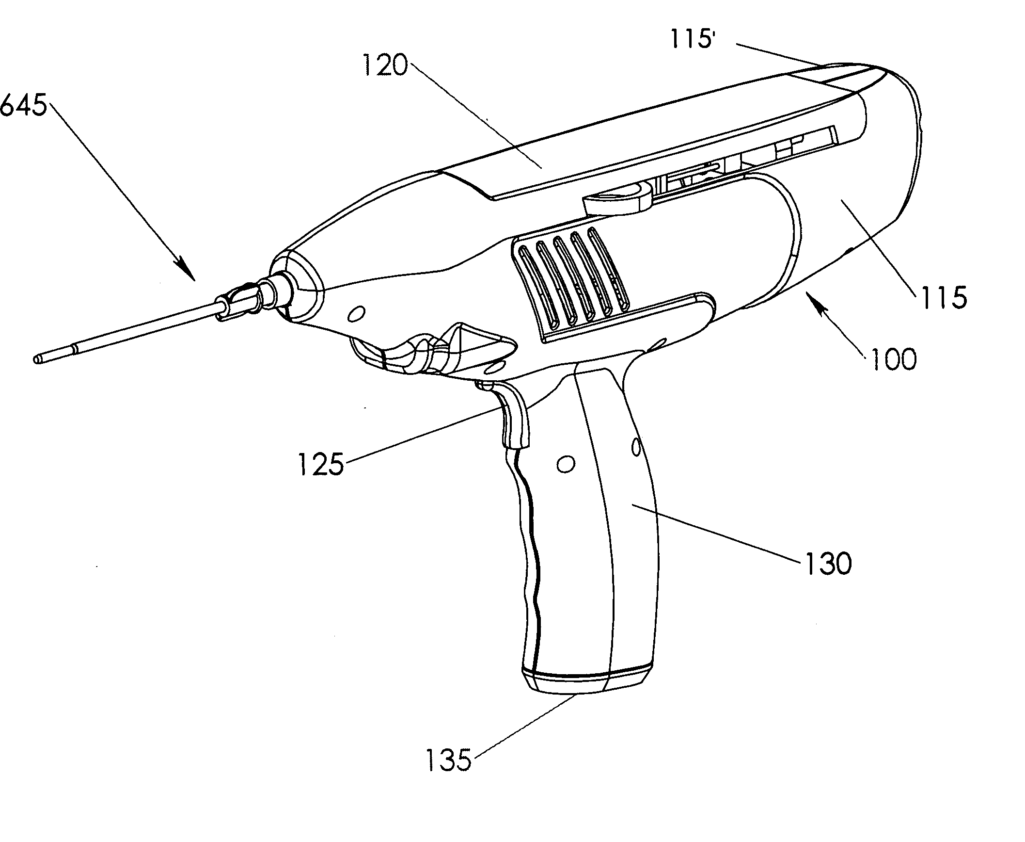
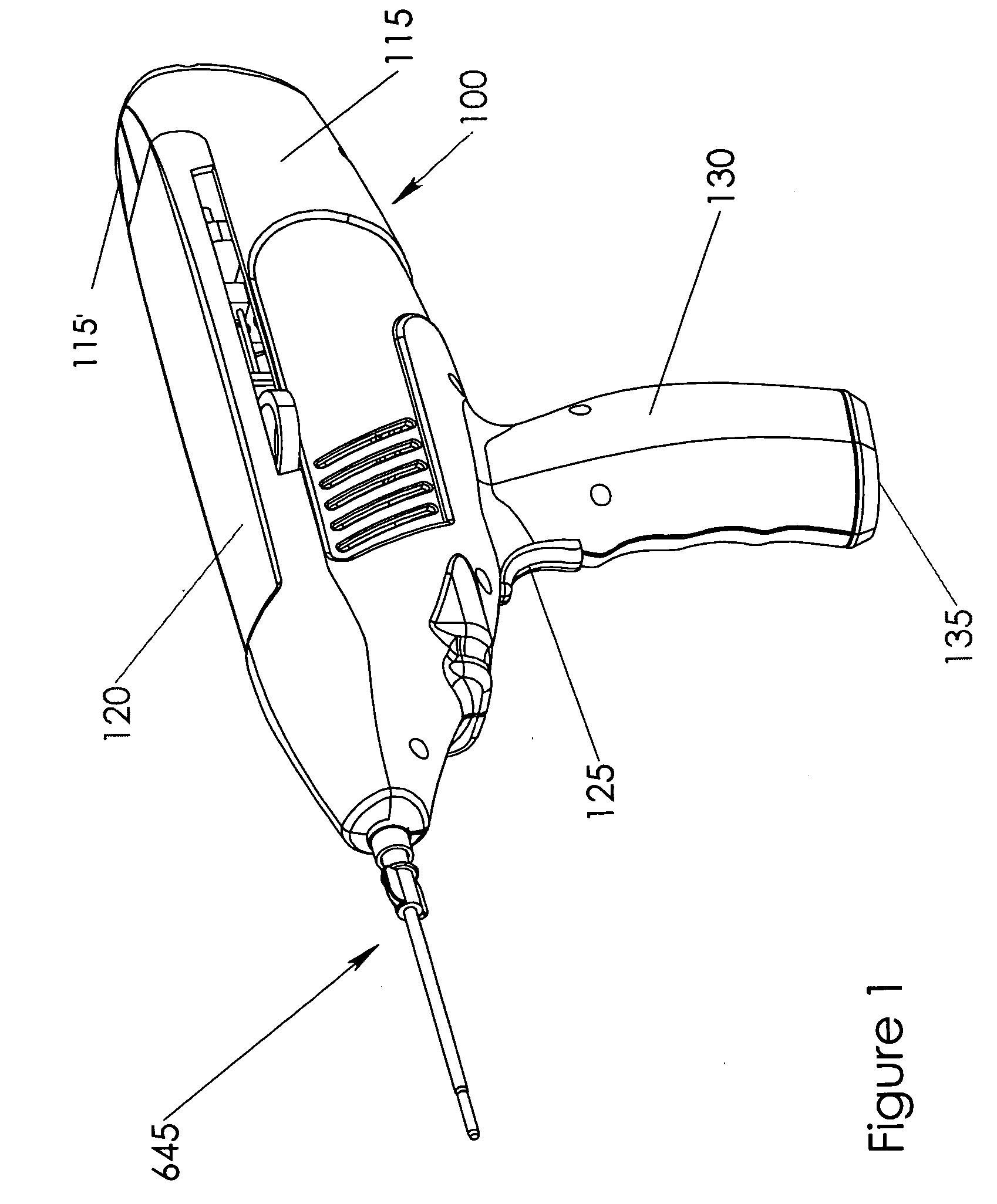
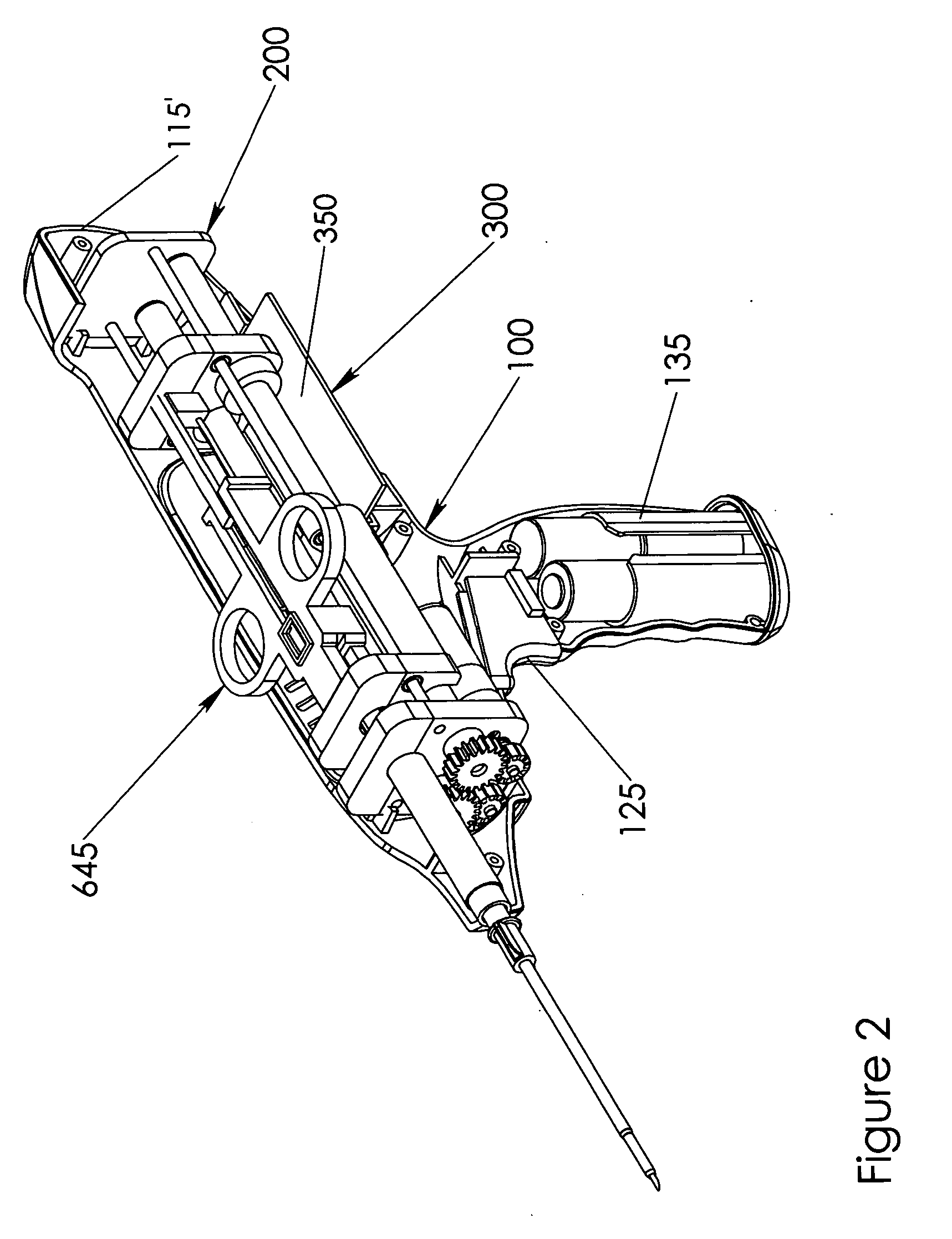
Automated biopsy and delivery device
a biopsy and automatic technology, applied in the field of automatic biopsy and delivery devices, can solve the problems of a long catheter procedure, a high complication rate of excision biopsies from other organs, and a high complication rate of excision biopsies from the lungs
- Summary
- Abstract
- Description
- Claims
- Application Information
AI Technical Summary
Benefits of technology
Problems solved by technology
Method used
Image

Examples
Embodiment Construction
[0042] It is advantageous to define several terms before describing the invention. It should be appreciated that the following definitions are used throughout this application.
[0043] For the purposes herein the term “biopsy” shall refer to the tissue sample retrieved from the body for evaluation of a possible disease tissue.
[0044] For the purposes herein the term “circuit boards” shall refer to any board, or other device that mechanically supports and electrically connects electronic components using any type of conductive pathway.
[0045] For the purposes herein the term “coagulant” shall refer to any material that the process of which causes blood to form solid clots.
[0046] For the purposes herein the term “cannula” shall refer to a thin walled tube.
[0047] For the purposes herein the term “hemostasis” shall refer to the stopping or arresting of bleeding.
[0048] For the purposes herein the term “mtor” shall refer to any device having the ability to convert a source of energy int...
PUM
 Abstract
Description
Claims
Application Information