Combined EGR valve and cooler by-pass

a cooler and egr valve technology, applied in the direction of machines/engines, process and machine control, fluid pressure control, etc., can solve the problem that the engine can be more expensiv

Inactive Publication Date: 2007-06-07
BORGWARNER INC
View PDF22 Cites 56 Cited by
  • Summary
  • Abstract
  • Description
  • Claims
  • Application Information

AI Technical Summary

Problems solved by technology

However, often time having two valves to perform the function of delivering exhaust gas to an EGR cooler, or bypass the EGR cooler and deliver the exhaust gas directly into the intake manifold of the engine can be more costly due to the increased amount of components, or may be limited by packaging constraints.

Method used


Image

  • Combined EGR valve and cooler by-pass
  • Combined EGR valve and cooler by-pass
  • Combined EGR valve and cooler by-pass

Examples


Embodiment Construction

[0015] The following description of the preferred embodiment(s) is merely exemplary in nature and is in no way intended to limit the invention, its application, or uses.

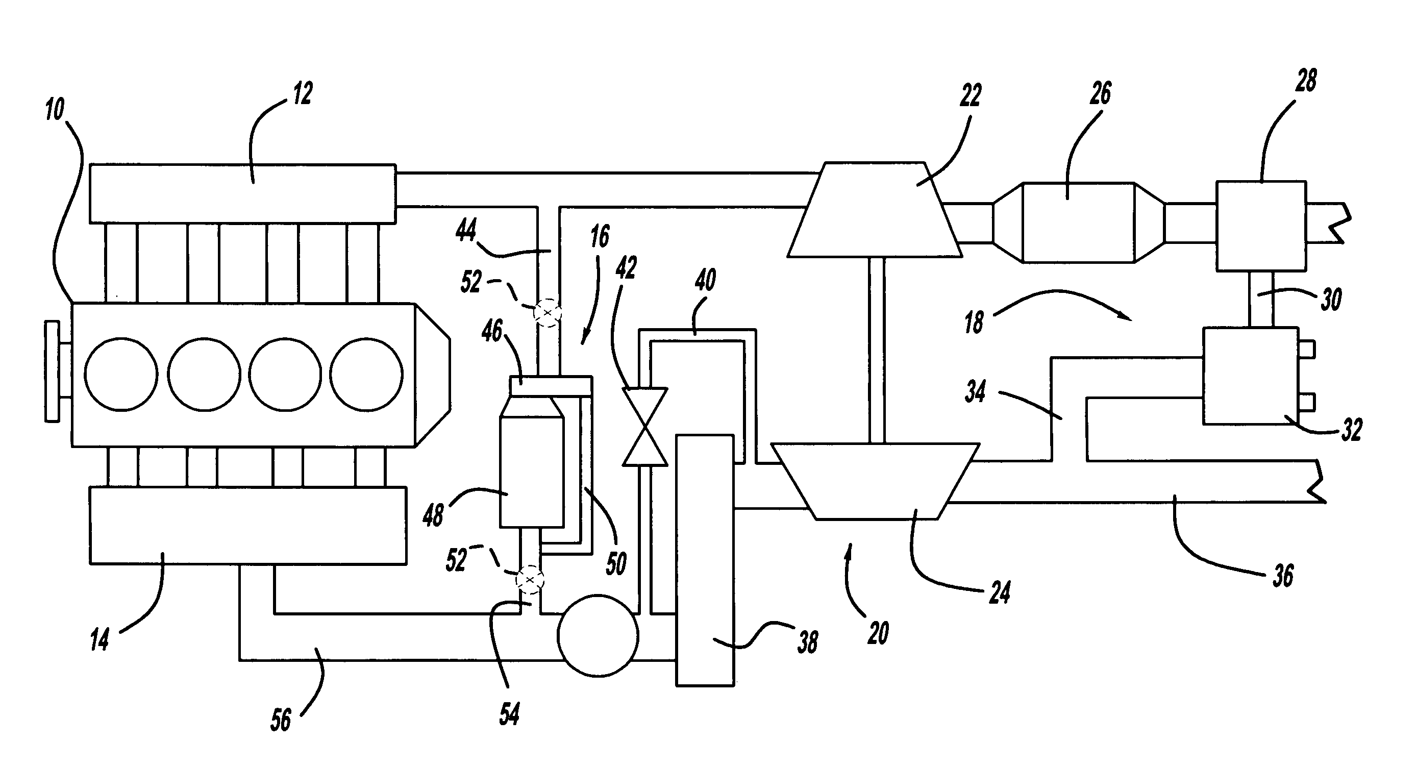
[0016] An engine 10 having an exhaust gas valve according to the present invention is shown in FIG. 1. The engine 10 has an exhaust manifold 12 and an intake manifold 14. There are two exhaust gas recirculation (EGR) loops, a high-pressure EGR loop 16, and a low-pressure EGR loop 18. The engine 10 also operates with the use of a turbocharger unit 20 which includes a turbine 22 and a compressor 24. The high-pressure EGR loop 16 is located upstream of the turbine 22 and downstream of the compressor 24, while the low-pressure EGR loop 18 is located downstream of the turbine 22, and upstream of the compressor 24.

[0017] Connected to the turbine 22 is a diesel particulate filter (DPF) 26 which receives exhaust gas from the turbine 22. The low-pressure EGR loop 18 includes a combined EGR and throttle valve 28, a first EGR...


PUM


Abstract

The present invention is an exhaust gas recirculation (EGR) valve for an engine having an exhaust gas recirculation cooler operable for receiving exhaust gas from an exhaust, and delivering the exhaust gas to an intake. The present invention also includes an exhaust gas recirculation bypass passage operable for receiving exhaust gas from an exhaust, bypassing the exhaust gas recirculation cooler, and delivering the exhaust gas to an intake, as well as a single valve operably associated with the exhaust gas recirculation cooler and the exhaust gas recirculation bypass passage. The single valve is selectively operable for opening or closing flow from the exhaust to the exhaust gas recirculation cooler, the exhaust gas recirculation bypass passage, or both, the single valve also operable for metering flow therebetween.

Description

CROSS-REFERENCE TO RELATED APPLICATIONS [0001] This application claims the benefit of U.S. Provisional Application No. 60 / 741,773, filed Dec. 2, 2005.FIELD OF THE INVENTION [0002] The present invention relates to EGR valves and their use in combination with an EGR cooler and an EGR cooler bypass valve. BACKGROUND OF THE INVENTION [0003] Future emissions requirements for Diesel Engines around the world will require engine concepts capable of achieving low NOx and low PM emissions while at the same time having a high integration of components / functions for low system cost and smallest package. Exhaust gas recirculation (EGR) valves and EGR cooler bypass valves are usually constructed as two separate valves. [0004] However, often time having two valves to perform the function of delivering exhaust gas to an EGR cooler, or bypass the EGR cooler and deliver the exhaust gas directly into the intake manifold of the engine can be more costly due to the increased amount of components, or may...

Claims


Application Information

Patent Timeline
Patent Type & Authority Applications(United States)
IPC IPC(8): F02B29/04F02B33/44
CPCF01N3/021F02B29/0406F02B29/0418F02B37/00F02M25/0707F02M25/0709F02M25/0712F02M25/0718F02M25/0719F02M25/0729F02M25/0732F02M25/0796Y02T10/121Y02T10/146Y02T10/144Y02T10/20F02M26/16F02M26/05F02M26/06F02M26/09F02M26/15F02M26/26F02M26/24F02M26/71Y10T137/86863Y10T137/87523Y02T10/12
Inventor CZARNOWSKI, ROBERTKIENER, TIMMJOERGL, VOLKER
Owner BORGWARNER INC
Why Eureka
Try Eureka