System for variable valvetrain actuation

a variable valvetrain and valvetrain technology, applied in the direction of valve drives, machines/engines, mechanical equipment, etc., can solve the problems of increasing the cost of the entire conventional engine, requiring significantly more power than a conventional fixed-state system, and unable to achieve the effect of simple, cost-effective and energy-saving variable valvetrain actuation system, and simplifying the task of design optimization

Inactive Publication Date: 2007-06-07
DELPHI TECH INC
View PDF6 Cites 27 Cited by
  • Summary
  • Abstract
  • Description
  • Claims
  • Application Information

AI Technical Summary

Benefits of technology

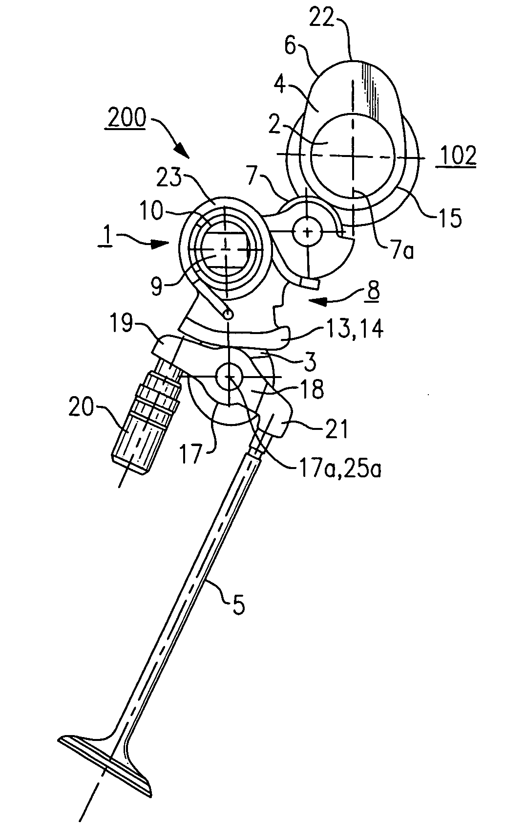
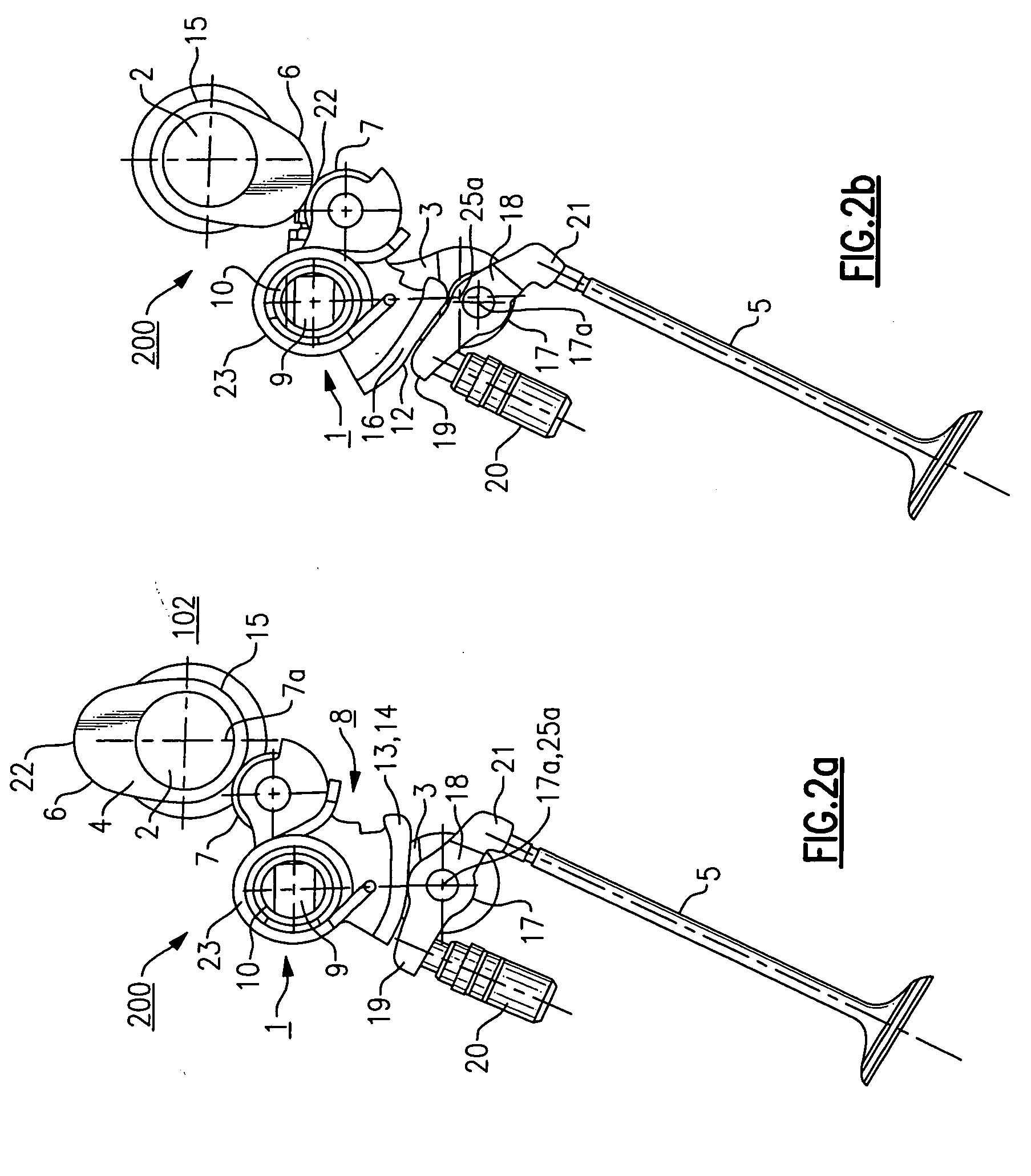
[0023] Compared to prior art devices, an important advantage of the present mechanism is its simplicity. The input and output oscillators of the prior art are continuously variable valvetrain devices, such as the SSCR and the DCDVVT, have been combined into one moving part. Due to its inherent simplicity, the present invention differs significantly from the original SSCR device in its assembly procedure for mass production. With only one oscillating member, the present invention accrues significant cost, manufacturing, and mechanical advantages over these previous designs. Further, a VVA device in accordance with the present invention does not “hang” from the camshaft, as is the case with these other mechanisms, but rather is supported on an engine head by its own arbors and journals, and therefore is not parasitic on the camshaft. Because there are fewer mechanical parts, there are fewer degrees of freedom in the mechanism. This simplifies the task of design optimization to meet performance criteria by substantially reducing the number of equations required to describe the motion of the present device. Further, a device in accordance with the invention requires approximately one-quarter the total number of parts as an equivalent SSCR device for a similar engine application. With its cost advantages and design flexibility, the present device can easily be applied to the intake camshaft of a gasoline engine for low cost applications, or to both the intake and exhaust camshafts of a Diesel or a gasoline HCCI engine.

Problems solved by technology

One of the drawbacks inhibiting the introduction of a gasoline Homogeneous Charge Compression Ignited (HCCI) engine in production has been the lack of a simple, cost effective, and energy-efficient Variable Valvetrain Actuation (VVA) system to vary one or both of the exhaust and intake events.
Many electro-hydraulic and electro-mechanical VVA systems have been proposed for gasoline HCCI engines, but while these systems may consume less or equivalent actuation power at low engine speeds, they typically require significantly more power than a conventional fixed-lift and fixed-duration valvetrain system to actuate at mid and upper engine speeds.
Moreover, the cost of these systems can approach the cost of an entire conventional engine itself.
As the cost of petroleum continues to rise from increased global demands and limited supplies, the fuel economy benefits of internal combustion engines will become a central issue in their design, manufacture, and use at the consumer level.
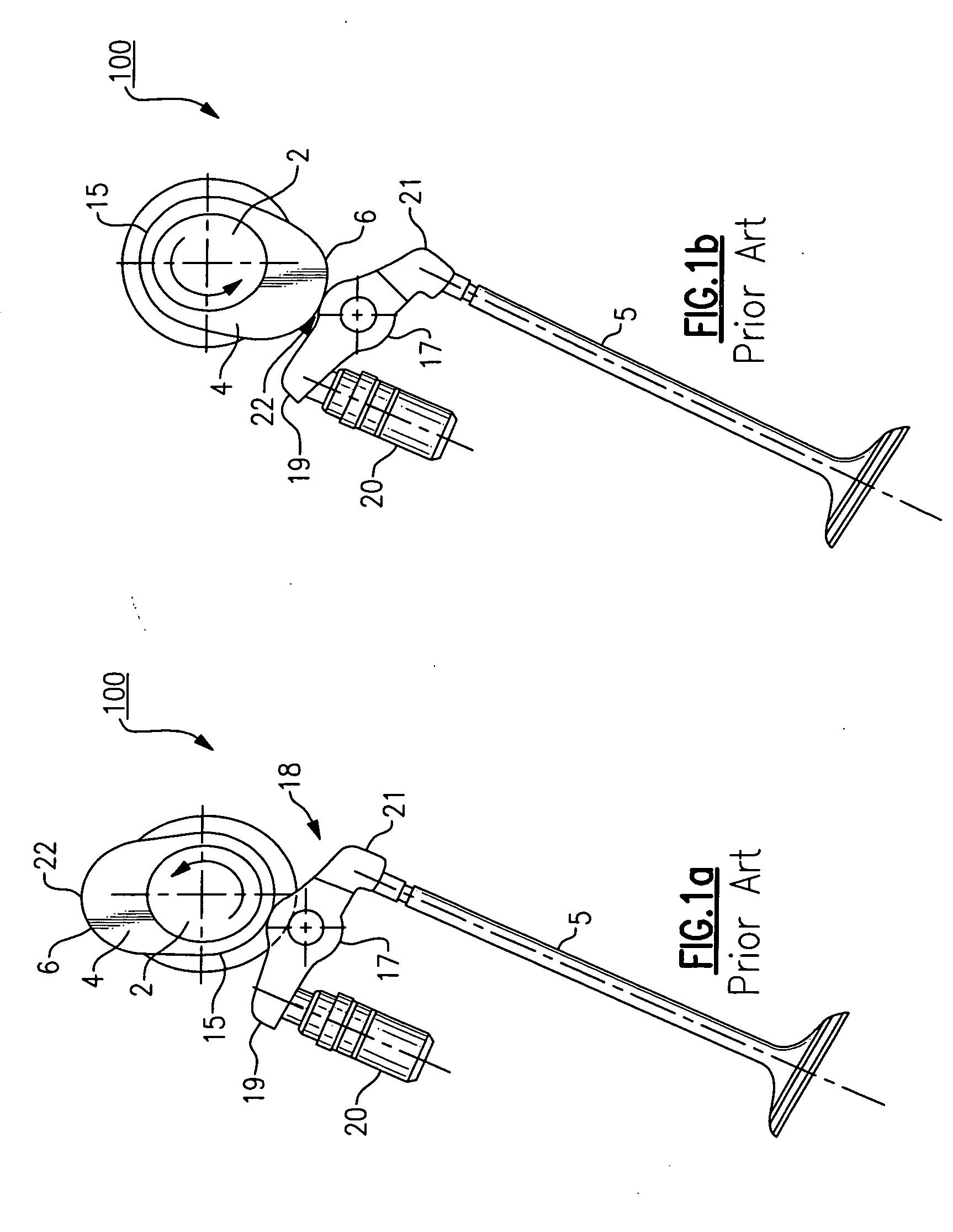
A shortcoming of these two prior art VVA systems is that both the SSCR device and the DCDVVT mechanism include two individual frame structures per each engine cylinder that are somewhat difficult to manufacture.
Another shortcoming is that the frame structures of these mechanisms “hang” from the engine camshaft and thus create a parasitic load.
Because the mechanism comprises four moving parts per cylinder, it is difficult to provide a return spring stiff enough for high-speed engine operation that can still fit in the available packaging space.
Still another shortcoming is that assembly and large-scale manufacture of such an SSCR device would be difficult at best with its large number of parts and required critical interfaces.
In the third example, while no indication is provided of a practical structure for implementing this arrangement, significant manufacturing and control complexity would exist in providing for, and controlling the action of, eccentric control shafts for both the intermediate and output elements.

Method used


Image

  • System for variable valvetrain actuation
  • System for variable valvetrain actuation
  • System for variable valvetrain actuation

Examples


embodiment 600

[0085] In embodiment 600, carrier control shaft 634 replaces the above described plurality of bolted together segments 34,35,36,37,38 forming a single control shaft for system 200. The individual crank elements in the form of pivot arms 603 and shank pins 625 are joined by bridges 641. The previous plurality of pivot pins 9 are replaced by a single rocker pivot shaft 609 that extends through bores 660 in carrier control shaft 634 to pivotably support rocker assemblies 608.

[0086] Each rocker subassembly 608 comprises a rocker frame 628 substantially the same as rocker frame 28 except that provision is made for replacement of bronze bearing insert 10 with a needle bearing assembly 610 to reduce friction of rocker subassembly 608 on rocker pivot shaft 609. Rocker roller 7, with shaft and bearing 33 is unchanged, as is return spring 23.

[0087] In operation, carrier control shaft rotates about the axis 627 of shank pins 625, thereby displacing rocker pivot shaft 609 through an angle 202 ...

embodiment 700

[0090] A base module 880 includes base sections 872, corresponding to base sections 772 in embodiment 700, joined by runners 882, each base section 872 including half-journals 884 for supporting shank pins 625 of VVA sub-assembly 600. Base module 880 may also include dowel pins 881 extending from the undersurface thereof to provide accurate alignment of the entire VVA assembly 800 with an engine head 891.

[0091] A main body module 884 includes a plurality of arbor center sections 874 corresponding to center sections 774 in embodiment 700, sections 874 being connected by runners 886, each arbor center section including upper half-bearings for shank pins 625, bottom half-bearings 888 for supporting camshaft 2, and slotted openings 890 for rocker pivot shaft 609. In one aspect of the invention, the width 893 of one or more slotted openings 890 may be sized to serve as positive end stops for shaft 609 as shaft 609 sweeps through its desired full arcuate path. Note that the slotted openin...


PUM


Abstract

An electromechanical VVA system for controlling the poppet valves in the cylinder head of an internal combustion engine. The system varies valve lift, duration, and phasing in a dependent manner for one or more banks of engine valves. A rocker subassembly for each valve is pivotably disposed in roller bearings on a rocker pivot shaft between the camshaft and a roller follower. A control shaft supports the rocker pivot shaft for controlling a plurality of rocker subassemblies mounted in roller bearings for a plurality of engine cylinders. The control shaft rotates about its axis to displace the rocker pivot shaft and change the angular relationship of the rocker subassembly to the camshaft, thus changing the valve opening, closing, lift and duration. An actuator attached to the control shaft includes a worm gear drive for positively rotating the control shaft.

Description

RELATIONSHIP TO OTHER APPLICATIONS AND PATENTS [0001] The present invention is a Continuation-In-Part of a pending U.S. patent application Ser. No. 11 / 294,223, filed Dec. 5, 2005.[0002] This invention was made with United States Government support under Government Contract / Purchase Order No. DE-FC26-05NT42483. The Government has certain rights in this invention.TECHNICAL FIELD [0003] The present invention relates to valvetrains of internal combustion engines; more particularly, to devices for controlling the timing and lift of valves in such valvetrains; and [0004] most particularly, to a system for variable valvetrain actuation wherein a mechanism for variable actuation is interposed between the engine camshaft and the valve train cam followers to vary the timing and amplitude of follower response to cam rotation. BACKGROUND OF THE INVENTION [0005] One of the drawbacks inhibiting the introduction of a gasoline Homogeneous Charge Compression Ignited (HCCI) engine in production has b...

Claims


Application Information

Patent Timeline
Patent Type & Authority Applications(United States)
IPC IPC(8): F01L1/34F01L1/02F01L1/18
CPCF01L1/024F01L1/185F01L1/267F01L13/0015Y10T74/2107F01L13/0063F01L2013/0068F01L2013/0073F01L2105/00F01L13/0021F01L1/08F01L2305/00
Inventor LEE, JONGMINROHE, JEFFREY D.
Owner DELPHI TECH INC
Why Eureka
Try Eureka