Oil pressure supply in an automatic transmission

a technology of automatic transmission and oil pressure supply, which is applied in the direction of gear lubrication/cooling, clutches, non-mechanical actuator clutches, etc., can solve the problems of increasing cost and troublesome assembly process, and achieve the effect of increasing the number of oil holes

Inactive Publication Date: 2007-06-07
AISIN AW CO LTD +1
View PDF8 Cites 11 Cited by
  • Summary
  • Abstract
  • Description
  • Claims
  • Application Information

AI Technical Summary

Benefits of technology

[0010] Accordingly, the present invention has as its object provision of an oil pressure supply structure in an automatic transmission by which the angular spacing (phase shift) between first and second oil holes, when a second drum is attached to a first drum, can be minimized without needlessly increasing the number of oil holes.

Problems solved by technology

To eliminate this variation in the clutch engagement time, the second oil holes 66 may be positioned in alignment with the first oil holes 65 when matching the inner drum within the outer drum, but such positioning requires marking the drums thereby adding a troublesome task to the assembly process and leading to an increase in cost.

Method used


Image

  • Oil pressure supply in an automatic transmission
  • Oil pressure supply in an automatic transmission
  • Oil pressure supply in an automatic transmission

Examples


Embodiment Construction

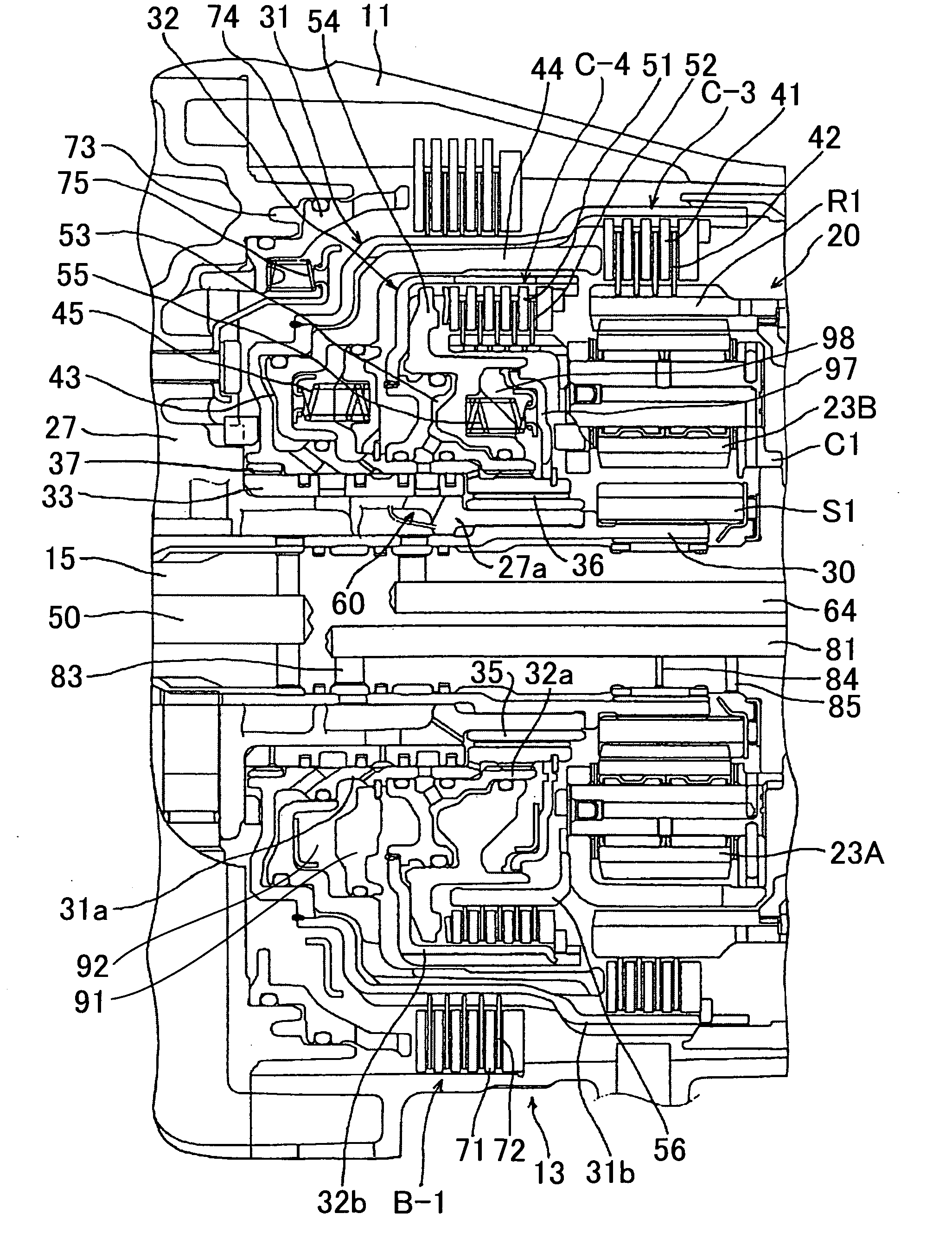
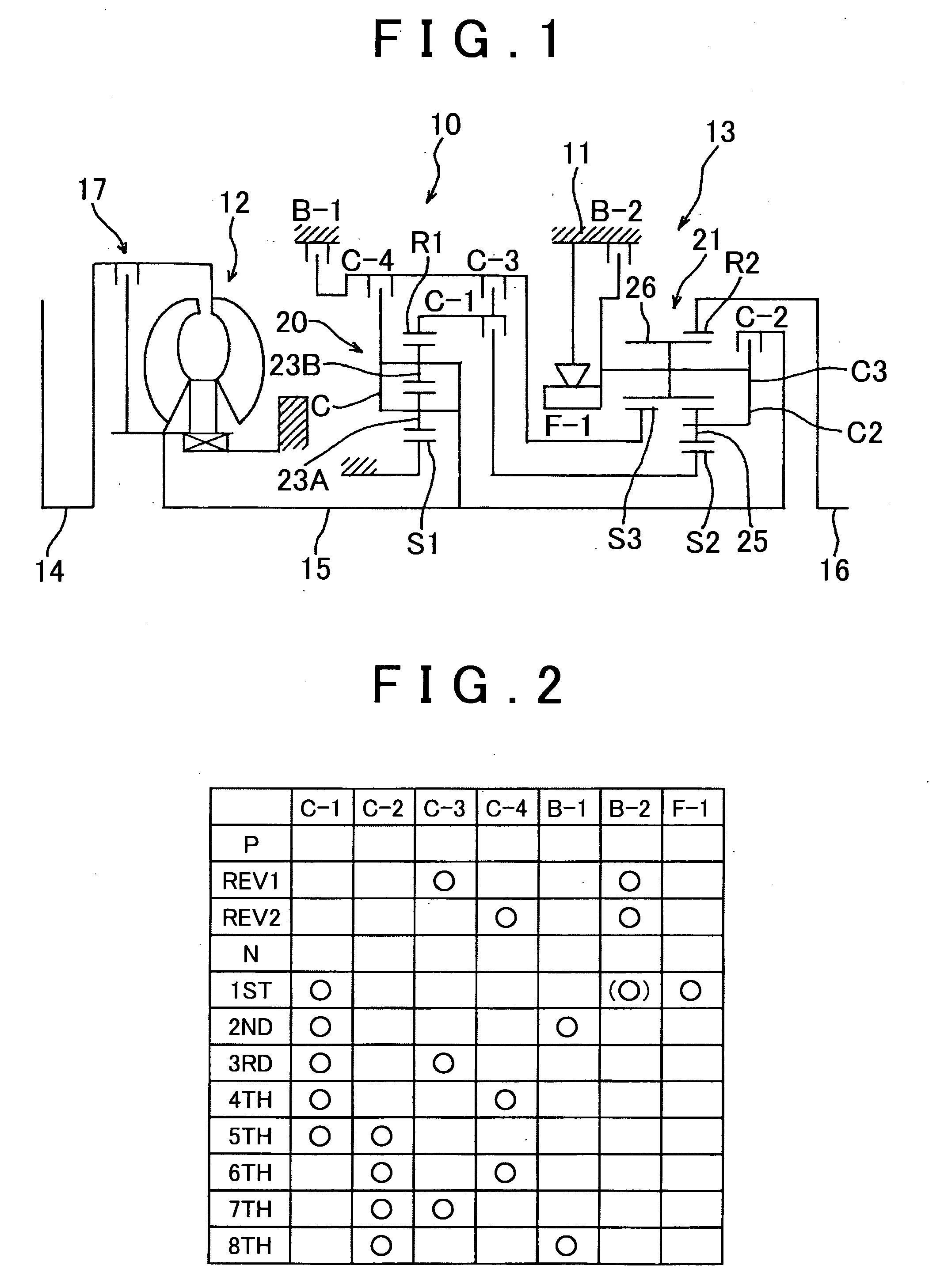
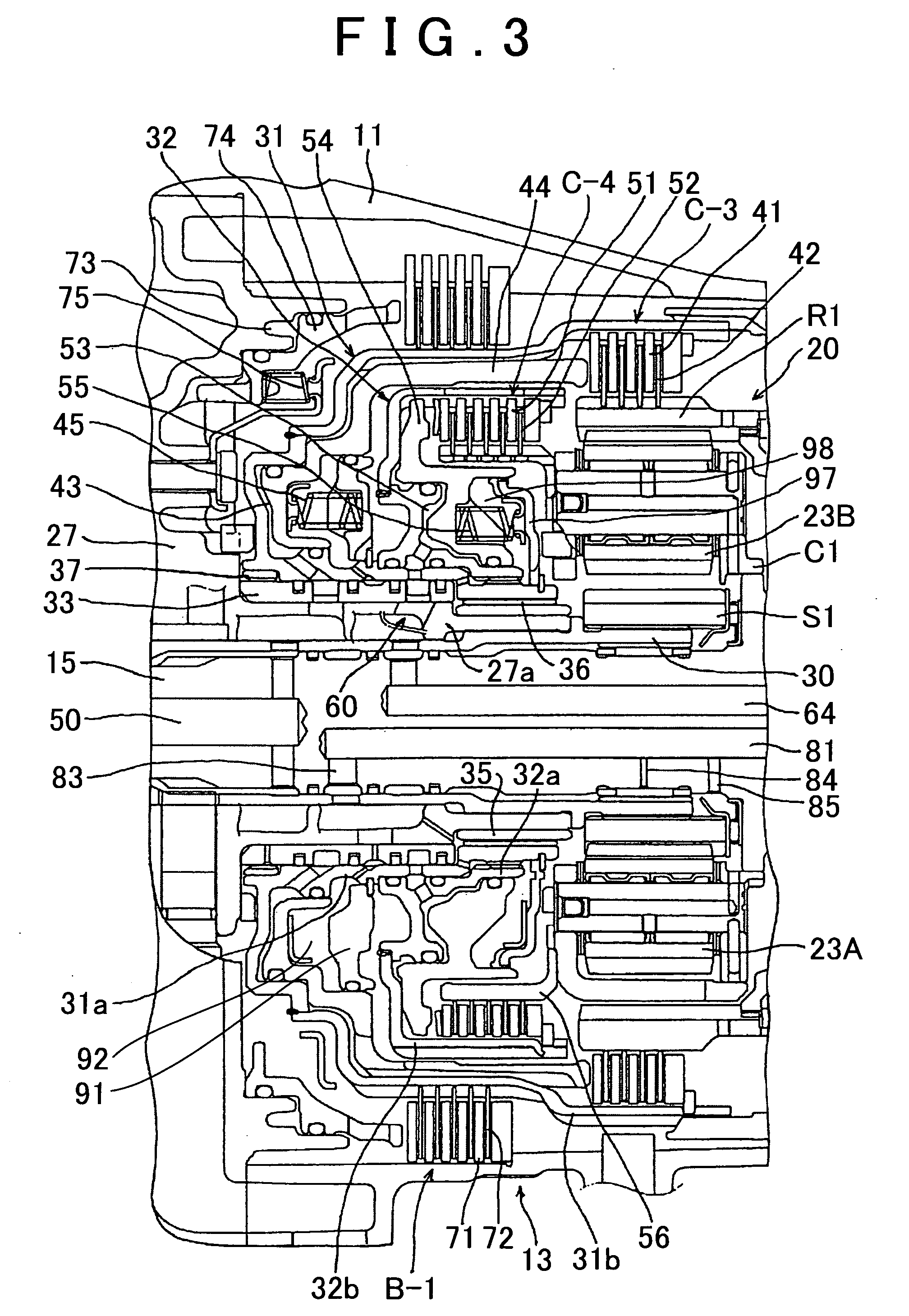
[0025] An embodiment of the present invention will be described below with reference to the drawings. FIG. 1 shows an automatic transmission 10 which is suitable for use in a front wheel or rear wheel drive type vehicle. The automatic transmission 10 is provided with a torque converter 12 and a speed change mechanism 13, both mounted in a transmission case 11 attached to a vehicle body. Output from the engine is input to an input shaft 15 of the automatic transmission 10 via the pump impeller and the turbine of the torque converter 12. The speed change mechanism 13 changes the speed of rotation input from the input shaft 15 and outputs the rotation at an output shaft 16 connected to a driven wheel. The torque converter 12 is provided with a lock-up clutch 17. Further, the input shaft 15 and output shaft 16 of the automatic transmission 10 are coaxial and aligned front to back of the vehicle. The torque converter 12 is disposed on the front end side of the transmission, while the out...


PUM


Abstract

An automatic transmission supplies oil pressure to a hydraulic servo of a second clutch through an oil pressure supply passage extending through a first drum and a second drum, the oil pressure supply passage including a plurality of first oil holes formed in the first drum at equal, circumferential intervals, a plurality of second oil holes formed in the second drum at equal, circumferential intervals, and an annular oil passage formed between the first and second drums and connecting the first oil holes and the second oil holes. The number of first oil holes is different from the number of second oil holes.

Description

INCORPORATION BY REFERENCE [0001] The disclosure of Japanese Patent Application No. JP2005-333338 filed on Nov. 17, 2005 including the specification, drawings and abstract is incorporated herein by reference in its entirety. BACKGROUND OF THE INVENTION [0002] 1. Field of the Invention [0003] The present invention relates to oil pressure supply structure in an automatic transmission for supplying oil pressure to a hydraulic servo of a clutch provided in the automatic transmission. [0004] 2. Description of the Related Art [0005] A conventional automatic transmission is provided with a plurality of clutches, each clutch including a drum, a piston, a canceller, and so on, as disclosed, for example, in Japanese Patent Application Publication No. JP-A-9-210088 (FIG. 2). [0006] Typically, two or more clutches are provided to achieve a plurality of shift speeds. To make the automatic transmission more compact, the clutches may share components. [0007] In an automatic transmission having a p...

Claims


Application Information

Patent Timeline
Patent Type & Authority Applications(United States)
IPC IPC(8): F16D25/00F16H57/04
CPCF16D25/0638Y10T74/19251F16H57/04F16D25/082F16D25/10
Inventor OKADA, NAOYAISHII, KUTSUHISAIWASE, MIKIOOTA, HIROFUMINOZAKI, KAZUTOSHIHONDA, ATSUSHI
Owner AISIN AW CO LTD
Why Eureka
Try Eureka