Radiation imaging apparatus, system and method as well as program

a technology of radiation imaging apparatus and system, applied in the field of radiation imaging apparatus, a system and a method as well as, to achieve the effects of reducing the occurrence of artifacts, simple configuration, and good quality

Inactive Publication Date: 2007-06-07
CANON KK
View PDF17 Cites 99 Cited by
  • Summary
  • Abstract
  • Description
  • Claims
  • Application Information

AI Technical Summary

Benefits of technology

[0018] According to the present invention, it become possible to restrain occurrence of artifact in an acquired radiation image with comparatively simple co...

Problems solved by technology

However, read data in the case where an X-ray is irradiated in the midst of “dummy read operation” gives rise to such a problem that leak phenomena through a switch take place to provide no accurate image signals since read operation is carried out...

Method used


Image

  • Radiation imaging apparatus, system and method as well as program
  • Radiation imaging apparatus, system and method as well as program
  • Radiation imaging apparatus, system and method as well as program

Examples


embodiment 1

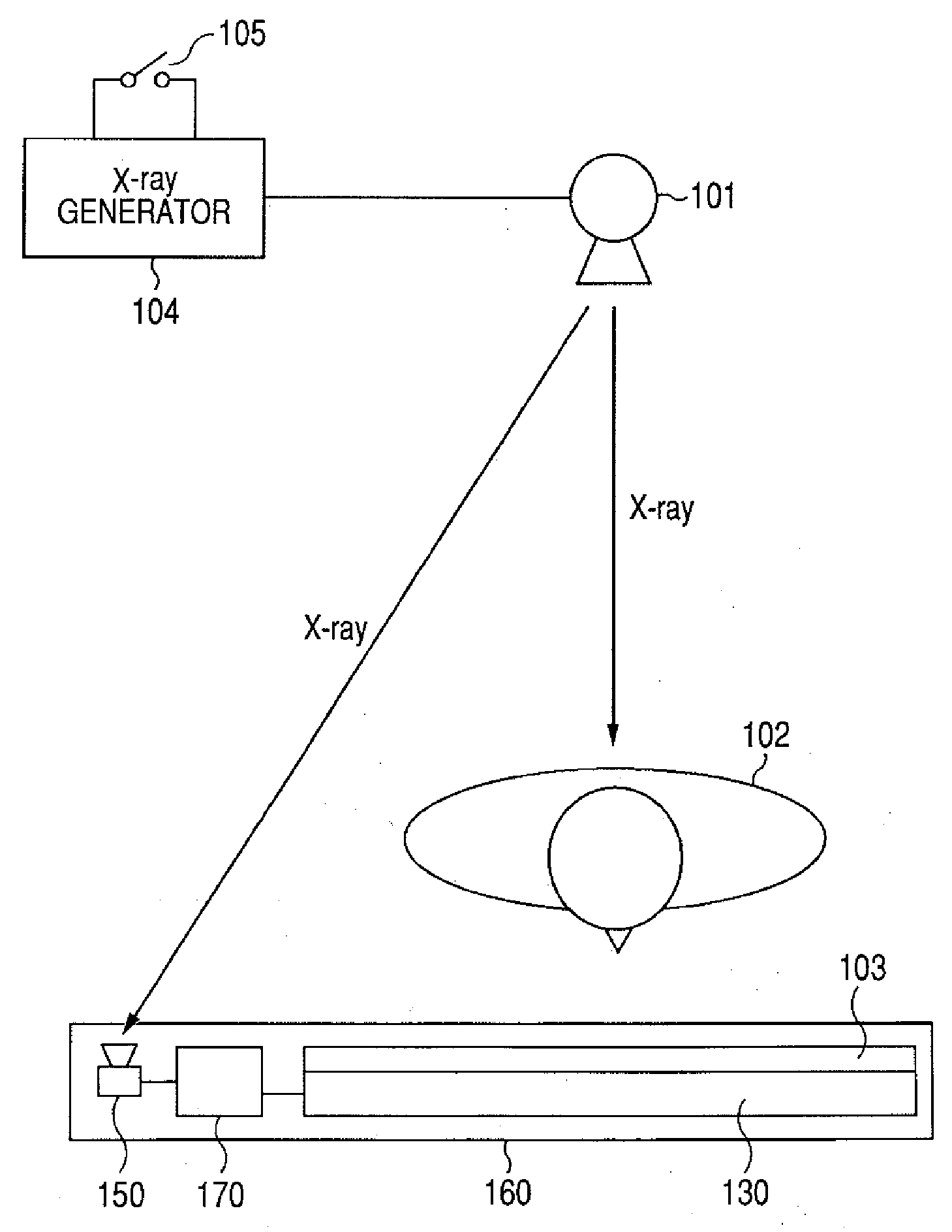
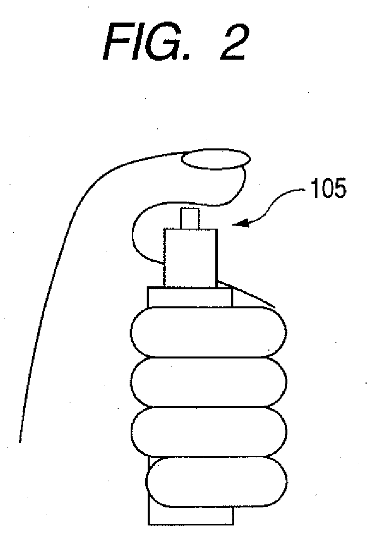
[0042]FIG. 3 is a schematic diagram schematically showing an X-ray imaging system according to an embodiment 1 of the present invention. In FIG. 3, reference numeral 101 denotes an X-ray source for outputting an X-ray; reference numeral 104 denotes an X-ray generator for generating an X-ray outputted from the X-ray source 101; and reference numeral 105 denotes a switch (an irradiation button) for controlling X-ray irradiation with which a radiographer and the like carry out opening / closing operation and is shaped as shown in FIG. 2. Reference numeral 103 denotes a phosphor which functions as a wavelength converter for converting an X-ray permeating an object 102 into light such as visible light and the like. Reference numeral 130 denotes an imaging apparatus mainly configured by a conversion circuit unit, a driving circuit unit and a signal processing circuit unit. The conversion circuit unit comprises a plurality of photoelectric conversion elements, which convert light converted w...

embodiment 2

[0073]FIG. 9 is a timing chart in the case where irradiation of an X-ray is started while a driving signal is in an ON state and is a drawing for showing an embodiment 2 of the present invention.

[0074] In FIG. 9, X-ray irradiation starts in the midst when a drive signal Vg3 is in the ON state. In the present embodiment, the drive signal Vg4 starts operation as real read operation with pulse width and timing likewise in FIG. 7 with no change after X-ray irradiation has finished. In this case, the X-ray image information portion of the portion where the drive signal Vg3 is stacked onto X-ray irradiation will be lost from the image of the drive signal Vg3. However, if X-ray irradiation period is set to sufficiently long period compared with the pulse width of the drive signal, the error amount thereof is small to an ignorable extent. Nevertheless, in the case where horizontally striped artifact is formed on an X-ray image to be obtained later, this is easily correctable by multiplying...

embodiment 3

[0076]FIG. 10 is a timing chart in the case where irradiation of an X-ray is started while a driving signal is in an ON state and is a drawing showing an embodiment 3 of the present invention. In FIG. 10, X-ray irradiation starts in the midst when a drive signal Vg3 is in the ON state. In the present embodiment, the dive signal Vg3 is forced OFF approximately at the same time with the start of X-ray irradiation. That method can be attained easily by tuning the OE signal OFF in FIG. 8, for example. The drive signal Vg4 starts operation as real read operation with timing likewise in FIG. 7. In case of the present embodiment, the portion where the drive signal Vg3 is stacked onto X-ray irradiation is extremely little and the loss of X-ray image information observed in embodiment 2 will never take place.

[0077] As having been described above, in the present embodiment, operation of providing that drive wiring with a drive signal is stopped in the case where the start of X-ray irradiatio...


PUM


Abstract

An object hereof is to restrain occurrence of artifact in an acquired radiation image with comparatively simple configuration without providing wiring between a radiation source and a radiation imaging apparatus to thereby obtain a radiation image with extremely good quality. Therefore, a controller selectively carries out real read operation of reading an electric signal obtained by activating a drive circuit from a signal processing circuit unit in case of detecting X-ray irradiation with an X-ray detecting circuit and dummy read operation of reading an electric signal obtained by activating a drive circuit from a signal processing circuit unit in case of detecting X-ray non-irradiation with an X-ray detecting circuit; discontinues the dummy read operation at the time of detecting the start of X-ray irradiation with the X-ray detecting unit in dummy read operation; and starts real read operation at the time of detecting the finish of X-ray irradiation with the X-ray detecting unit.

Description

BACKGROUND OF THE INVENTION [0001] 1. Field of the Invention [0002] The present invention relates to a radiation imaging apparatus, a system and a method as well as a program preferable for use in medical diagnosis and industrial non-destructive inspection. As described herein, a radiation is intended to include electromagnetic waves such as X-rays and γ-rays, α-rays, and β-rays. [0003] 2. Description of the Related Art [0004] Conventionally, an X-ray imaging system installed in a hospital and the like is divided into an analog system that irradiates a patient with an X-ray and irradiates film with the X-ray having penetrated a patient and a digital system that irradiates a patient with X-ray and converts an X-ray having penetrated a patient into an electric signal and accumulates it. [0005] In FIG. 16, reference numeral 101 denotes an X-ray source of irradiating an X-ray; reference numeral 104 denotes an X-ray generator of generating X-rays outputted from the X-ray source 101; refe...

Claims


Application Information

Patent Timeline
IPC IPC(8): G01T1/20G01T1/24
CPCG01T1/17H04N5/32H04N5/357H04N25/60
Inventor ENDO, TADAOKAMESHIMA, TOSHIOYAGI, TOMOYUKITAKENAKA, KATSUROYOKOYAMA, KEIGO
Owner CANON KK
Why Eureka
Try Eureka