
Method of manufacturing integrated bipolar plate/diffuser components for proton exchange membrane fuel cells

Inactive Publication Date: 2007-06-07
NANOTEK INSTR GRP LLC
View PDF5 Cites 14 Cited by
  • Summary
  • Abstract
  • Description
  • Claims
  • Application Information

AI Technical Summary

Benefits of technology

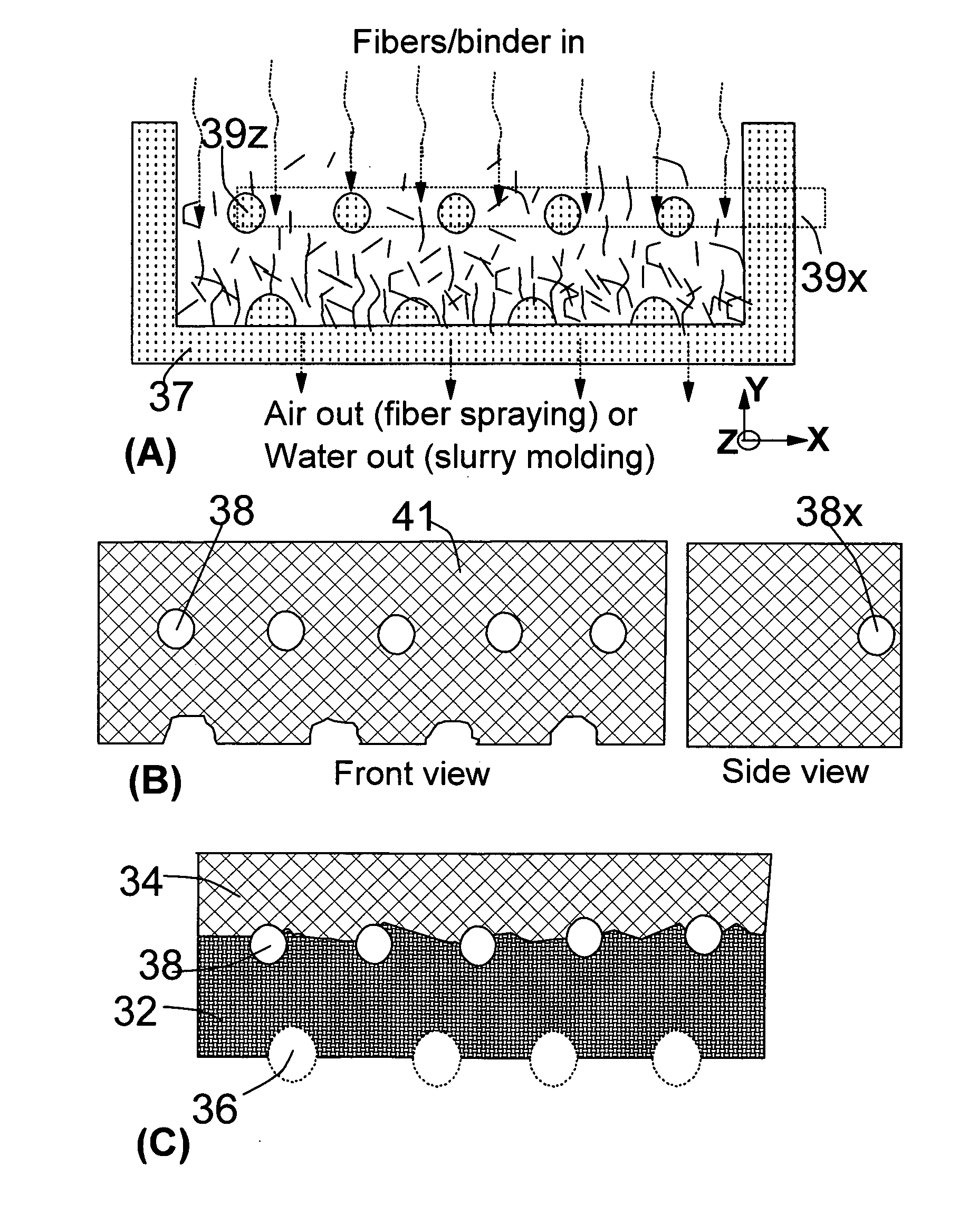
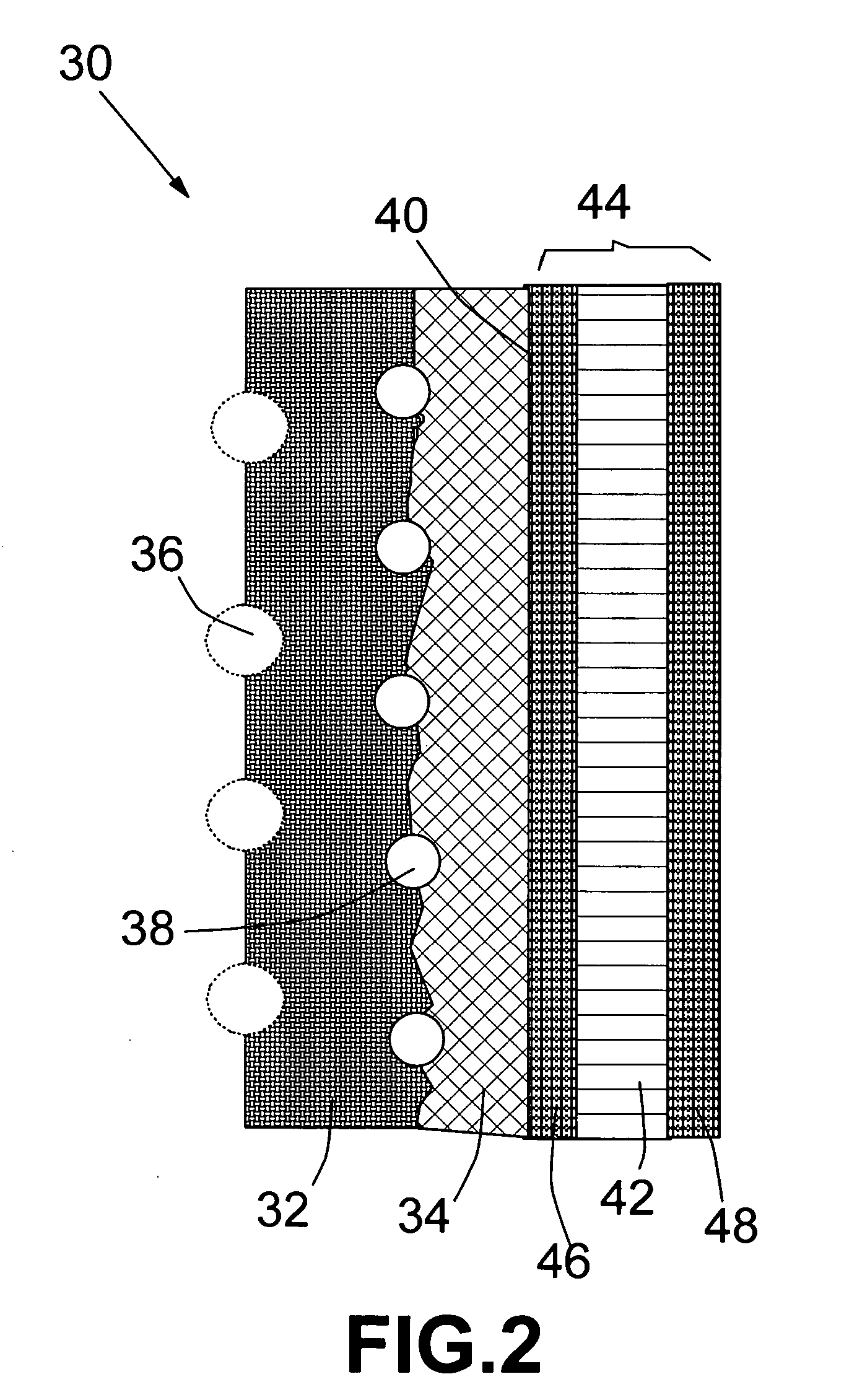
[0010] The present invention provides a method of producing an integrated bipolar plate / diffuser fuel cell component, which comprises a monolith of electrically conducting, partially impregnated preform material having: (a) a porous region (serving as a diffuser for fuel or oxidant) having a porous surface (in contact with an electro-catalyst) and (b) a hermetic region infiltrated with a matrix material containing no chemical vapor infiltration-densified carbon. The hermetic region defines at least a portion of a coolant channel. It acts to prevent mixing of fuel and oxidant. The porous region defines at least a portion of a reactant channel, as well as a flow field medium for diffusing a reactant to the porous surface. This component can be mass-produced at a fast rate, leading to a reduction in over-all fuel cell cost. The integrated component has a reduced contact resistance or ohmic loss, resulting in a higher output voltage and power. The method comprises the steps of: (a) directing a stream of precursor material into a molding tool, wherein the stream of precursor material comprises a mixture of an electrically conductive fiber, a binder, and a carrier fluid; (b) molding the precursor material into a monolithic preform having a porous region having a porous surface, and at least one reactant channel; (c) curing or solidifying the binder to impart a desired level of rigidity to the preform; and (d) infiltrating a portion of the porous region with a matrix material to form a hermetic region of the preform to obtain the bipolar plate / diffuser fuel cell component. The method does not involve tedious and expensive chemical vapor infiltration of carbon into the preform.
[0011] The present invention also provides a method of producing an integrated bipolar plate / diffuser fuel cell component, which comprises a monolith of electrically conducting, partially impregnated preform material having (a) a first porous region having a first porous surface; (b) a second porous region having a second porous surface; and (c) a hermetic region infiltrated with a matrix material containing no chemical vapor infiltration-densified carbon. The hermetic region defines at least one coolant channel and the first porous region defines at least a portion of at least one fuel channel. The second porous region defines at least a portion of at least one oxidant channel. The first porous region further defines a flow field medium for diffusing the fuel to the first porous surface and the second porous region defines a flow field medium for diffusing the oxidant to the second porous surface. This is an integrated component that provides three functions: fuel delivery and distribution, coolant transport, and oxidant delivery and distribution. This component also can be mass produced with a relatively low cost as compared to the process that involves chemical vapor infiltration.

Problems solved by technology

The bipolar plate is known to significantly impact the performance, durability, and cost of a fuel cell system.
The bipolar plate, which is typically machined from graphite, is one of the most costly components in a PEM fuel cell.
It is well-known that CVI is a very time-consuming and energy-intensive process and the resulting carbon / carbon composite, although exhibiting a high electrical conductivity, is very expensive.

Method used


Image

  • Method of manufacturing integrated bipolar plate/diffuser components for proton exchange membrane fuel cells
  • Method of manufacturing integrated bipolar plate/diffuser components for proton exchange membrane fuel cells
  • Method of manufacturing integrated bipolar plate/diffuser components for proton exchange membrane fuel cells

Examples


Embodiment Construction

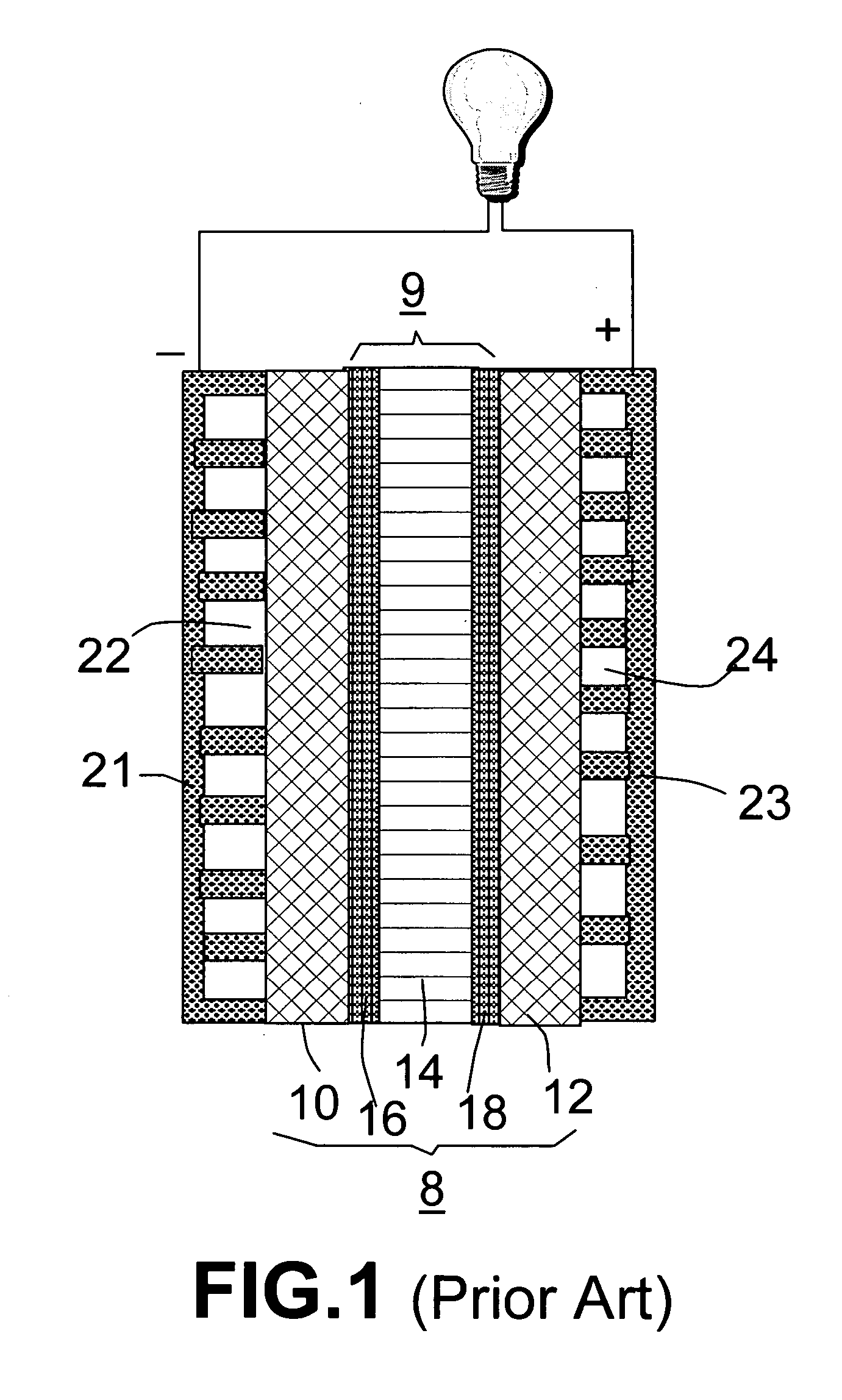
[0017] A prior art fuel cell, as shown in FIG. 1, typically comprises a membrane electrode assembly 8, which comprises a proton exchange membrane 14 (PEM), an anode backing layer 10 connected to one face of the PEM 14, and a cathode backing layer 12 connected to the opposite face of PEM 14. Anode backing layer 10 is also referred to as a fluid diffusion layer or diffuser, typically made of carbon paper or carbon cloth. A platinum / ruthenium electro-catalytic film 16 is positioned at the interface between the anode backing layer and PEM 14 for promoting oxidation of the methanol fuel. Similarly, at the cathode side, there are a backing layer or diffuser 12 (e.g., carbon paper or carbon cloth) and a platinum electro-catalytic film 18 positioned at the interface between the cathode backing layer and PEM 14 for promoting reduction of the oxidant.

[0018] In practice, the proton exchange membrane in a PEM-based fuel cell is typically coated on both sides with a catalyst (e.g., Pt / Ru or Pt)...


PUM

PropertyMeasurementUnit
Temperatureaaaaaaaaaa
Lengthaaaaaaaaaa

Abstract

A method of making an integrated bipolar plate / diffuser fuel cell component comprising the steps of: (a) directing a stream of precursor material into a molding tool, wherein the stream of precursor material comprises a mixture of an electrically conductive fiber, a binder, and a carrier fluid; (b) molding the precursor material into a monolithic preform having a porous region having a porous surface, and at least one reactant channel; (c) curing or solidifying the binder to impart a desired level of rigidity to the preform; and (d) infiltrating a portion of the porous region with a matrix material to form a hermetic region of the preform to obtain the bipolar plate / diffuser fuel cell component, wherein the matrix material contains no chemical vapor infiltration carbon. This component can be mass-produced at a fast rate with a relatively low cost. The integrated component has a reduced contact resistance or ohmic loss when used in a fuel cell system.

Description

[0001] The present invention is based in part on the research results of a project supported by the DoE SBIR Program. The US government has certain rights on this invention.FIELD OF THE INVENTION [0002] The present invention relates to a method of producing integrated bipolar plate / diffuser components for proton exchange membrane fuel cells. The bipolar plate and diffuser functions are combined into a monolithic body that is mass-produced in a net-shape manner. BACKGROUND OF THE INVENTION [0003] A fuel cell converts chemical energy into electrical energy and some thermal energy by means of a chemical reaction between a fuel (e.g., hydrogen gas or a hydrogen-containing fluid) and an oxidant (e.g., oxygen). A proton exchange membrane (PEM) fuel cell uses hydrogen or hydrogen-rich reformed gases as the fuel, a direct-methanol fuel cell (DMFC) uses methanol-water solution as the fuel, and a direct ethanol fuel cell (DEFC) uses ethanol-water solution as the fuel, etc. These types of fuel...

Claims


Application Information

Patent Timeline
IPC IPC(8): C01B31/02
CPCH01M8/0213H01M8/0221H01M8/0226H01M8/0234H01M8/0239H01M8/0243H01M8/0245H01M8/0267Y02E60/50H01M8/0258Y02P70/50
Inventor ZHAMU, ARUNAJANG, BOR Z.
Owner NANOTEK INSTR GRP LLC
Learn More