
Universal output device control

a technology of output device and control device, which is applied in the direction of digital output to print units, instruments, digitally marking record carriers, etc., can solve the problems of failing to take advantage of advanced capabilities of various devices, and it is more difficult for a given user to access output devices, so as to facilitate the entry of output device options

Active Publication Date: 2007-06-07
LEXMARK INT INC
View PDF7 Cites 69 Cited by
  • Summary
  • Abstract
  • Description
  • Claims
  • Application Information

AI Technical Summary

Benefits of technology

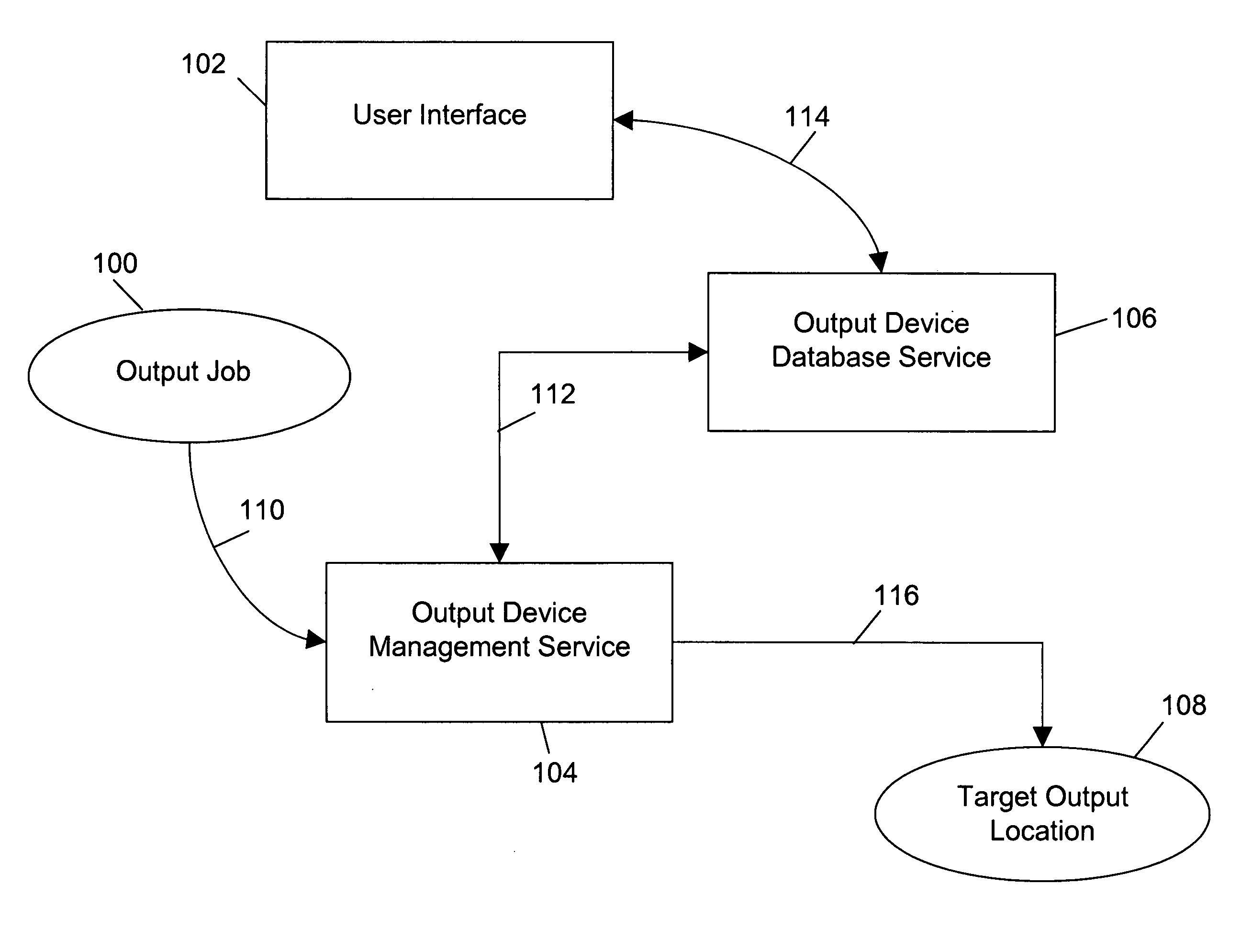
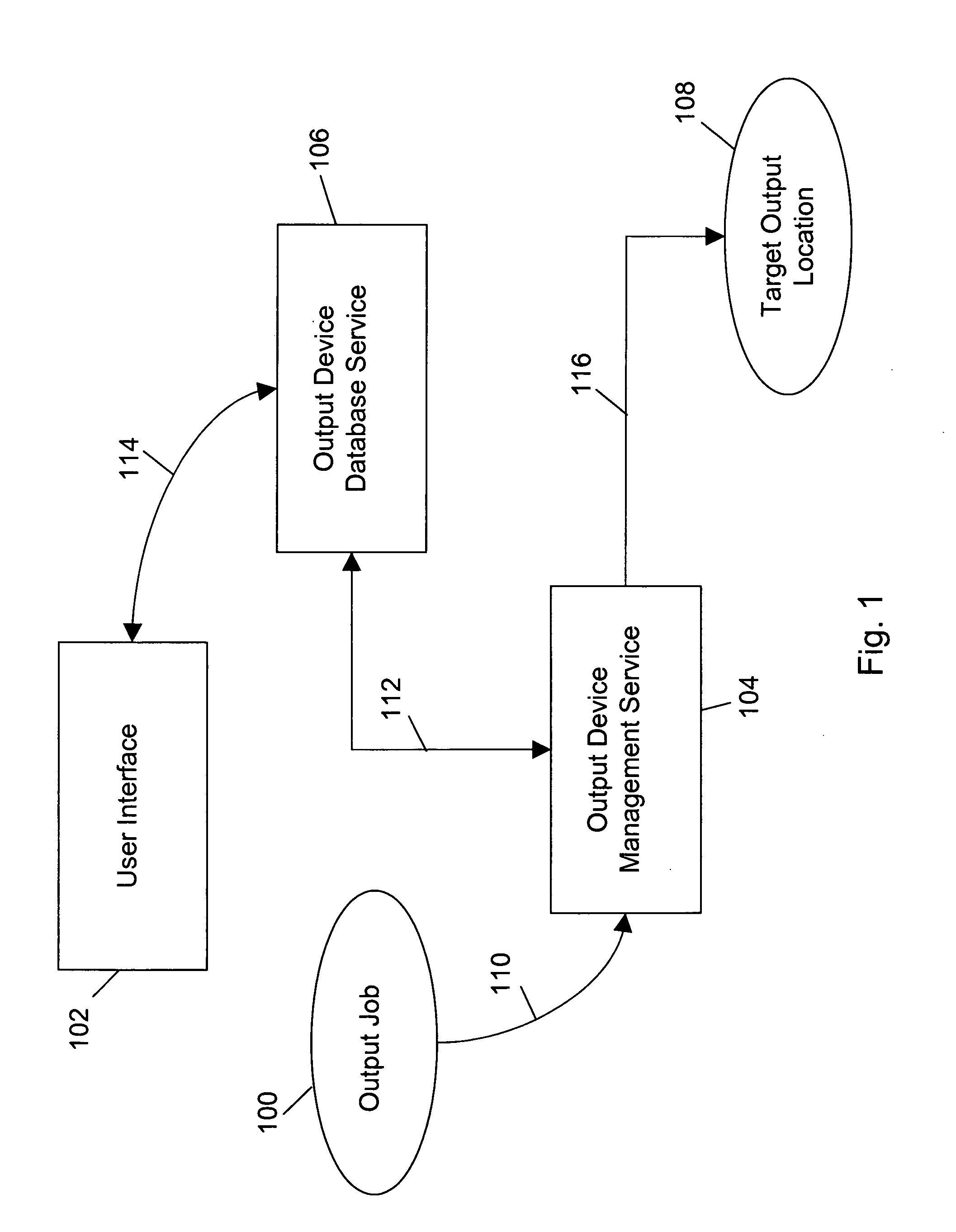
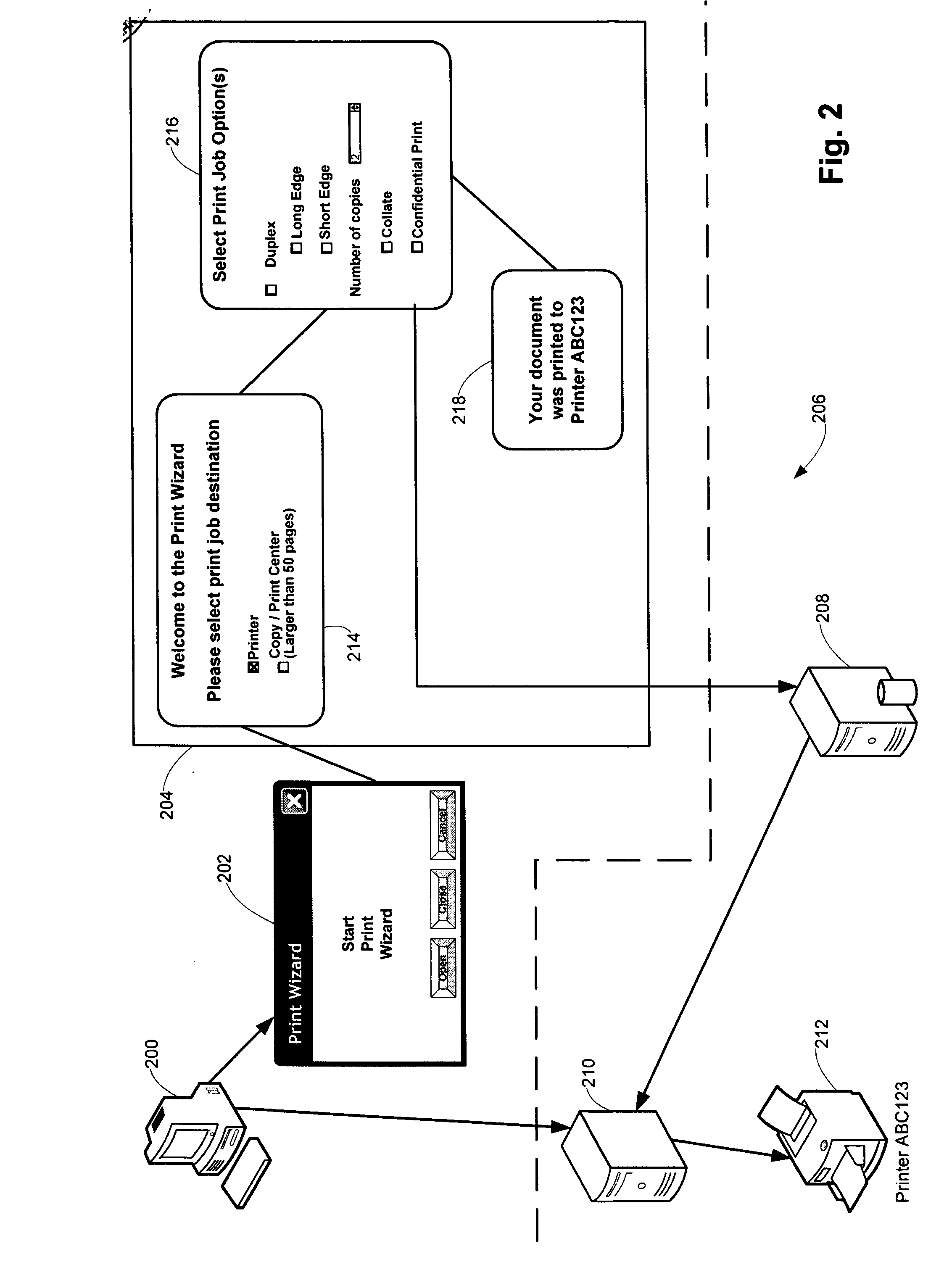
[0008] In an alternative embodiment, an output device management application service stores an output job, such as a text document, to be output, such as printed, on a selected output device, such as a printer. A user interface facilitates the entry of output device options needed to output the output job on the selected output device. The selected output device may either be directly connected to the user via a network or may be located at an output center, such as FedEx Kinkos. The user interface provides a common set of command options for a common class of output devices, thereby encapsulating all of the output device details from the user. The information submitted by the user through the user interface is then translated into job data specific for the selected output device. The job data are then combined with the output job in order to create a device specific integrated output job. The integrated output job is then rendered into either a tangible form, such as printed, or an alternative electronic form, such as a facsimile by the selected output device.

Problems solved by technology

The interconnectivity of computers and output devices, however, makes it more difficult for a given user to access the output devices.
Thus, in many network environments, users will frequently only use a small number of the available output devices and will fail to take advantage of advanced capabilities of various devices.

Method used


Image

  • Universal output device control
  • Universal output device control
  • Universal output device control

Examples


Embodiment Construction

[0018]FIGS. 1-5 show a first embodiment of the universal output device control system of the present invention. FIG. 1 is a block diagram showing the functional elements of the present invention and their interconnections. The output data file, generic output, print job, or more generally, output job 100 to be submitted for output on a target object location 108 is prepared by the user using his / her normal processes. The target object location 108 is either an output device, such as a printer, facsimile, or multi-function device capable of performing printing in addition to at least one other function such as scanning, copying or faxing, that is connected directly via a network or is an output device located at a third party vendor, or output center, such as a FedEx Kinko's or UPS store.

[0019] An output job 100, such as a document or file, targeted for output on a printer may be pre-processed and encoded in device independent formats such as Postscript, Printer Command Language (PC...


PUM


Abstract

A universal output control system and method for outputting an output job at a target output location wherein a universal user interface facilitates access to and control of a plurality of output devices located on a network or at an output center such that specific details of each output device are encapsulated. The universal user interface provides searches of available output devices in a network, wherein printer drivers are automatically installed as needed. Alternatively, an output management application service stores an output job until output job data is generated for controlling the output of the output job on the selected output device, at which time the output job is output on the selected output device per the output job data. If the target output location is an output device on a network, an output device database service captures and generates the output job data. If the target output location is an output device at an output center, an output center interface is launched for capturing and generating the output job data.

Description

FIELD OF THE INVENTION [0001] The present invention relates generally to methods, devices, and processes for controlling distributed output devices and services on personal, local, and wide area networks, with application to a print control system and method having a common user interface for providing access to one or more output devices and services of varying format. BACKGROUND OF THE INVENTION [0002] Electronic information stored in and manipulated with computerized devices are often output into either a tangible form or transformed into another electronic data format for transport using different systems. Computerized devices can include, but are not limited to, workstations, laptops, servers, personal digital assistants, and a multitude of other devices that can all be referred to generally as “computers.” Computer users have access to a multitude of methods for outputting information including generating hardcopy through different printing means such as laser, inkjet, wax tra...

Claims


Application Information

Patent Timeline
IPC IPC(8): G06F3/12
CPCG06F3/1204G06F3/1226G06F3/1229G06F3/1288B33Y50/00G06F15/00
Inventor STEELE, JOHN S.GHAZALIAN, EDWARD B.
Owner LEXMARK INT INC
Learn More