Light source device and projector

a light source device and projector technology, applied in the direction of lighting and heating apparatus, semiconductor devices for light sources, instruments, etc., can solve the problems of short lifetime of high-pressure mercury lamps, difficult to promptly turn on high-pressure mercury lamps, and badly affect the size and weight of projectors, so as to enhance the utilization efficiency of light. , the effect of enhancing the utilization efficiency of ligh

Inactive Publication Date: 2007-06-07
FUJI PHOTO OPTICAL CO LTD
View PDF2 Cites 19 Cited by
  • Summary
  • Abstract
  • Description
  • Claims
  • Application Information

AI Technical Summary

Benefits of technology

[0014] In the light source device according to the invention, light, which are emitted widely from the solid light-emitting elements, can be distributed by the use of the light distribution members disposed correspondingly to the solid light-emitting elements, which emits the red light, the green light, and the blue light, respectively. In addition, since at least one of the light distribution members has a configuration different from those of the other light distribution members. The at least one of the light distribution members is configured in accordance with the light distribution characteristic of the corresponding one of the solid light emitting elements, which varies depending on the emitted colors and the shape of the solid light-emitting element. Therefore, i

Problems solved by technology

However, since the high-pressure mercury lamp requires a large and heavy drive circuit, it badly affects decrease in size and weight of a projector.
Since the high-pressure mercury lamp takes time for start-up, it is difficult to promptly turn on the high-pressure mercury lamp.
In addition, a lifetime of the high-pressure mercury lamp is short.
In addition, since the emission brightness is enhanced with the recent development, the lifetime is long and the power consumption is

Method used


Image

  • Light source device and projector
  • Light source device and projector
  • Light source device and projector

Examples


Embodiment Construction

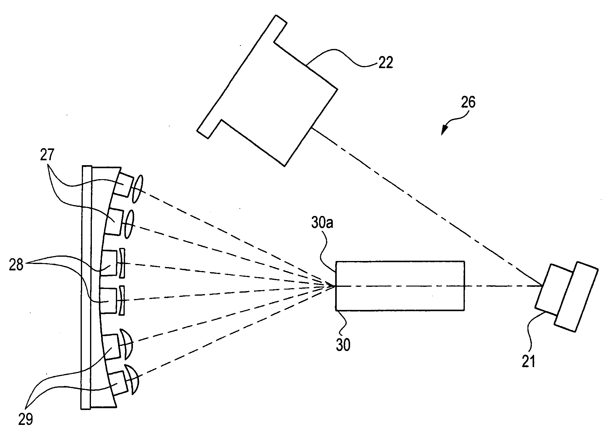
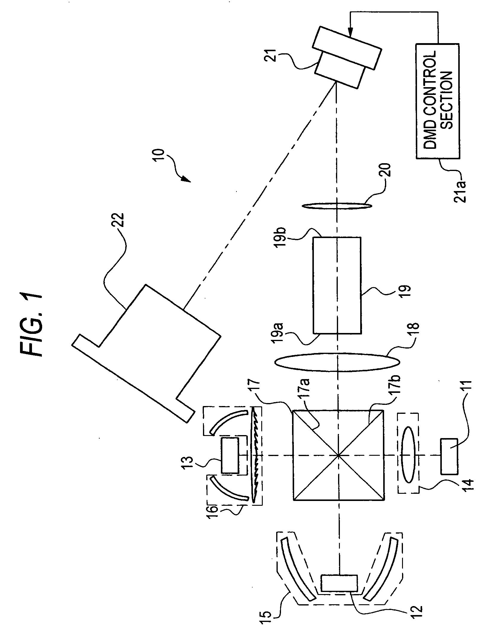
[0027] As shown in FIG. 1, a DLP (digital light processing) 10 includes: an R-light LED chip 11 (solid light-emitting element) for emitting R light (red); a G-light LED chip 12 (solid light-emitting element) for emitting G light (green); a B-light LED chip 13 (solid light-emitting element) for emitting B light (blue); an R-light optical system 14 (light distribution member) for the R-light LED chip 11; a G-light optical system 15 (light distribution member) for the G-light LED chip 12; a B-light optical system 16 (light distribution member) for the B-light LED chip 13; a cross dichroic prism 17; a condenser lens 18; a rod integrator 19; a relay lens 20; a DMD 21 (light modulation unit); and a projection lens 22 (projection optical system).

[0028] The R, G, and B light emitted from the R-light LED chip 11, the G-light LED chip 12, and the B-light LED chip 13 are all incident on the cross dichroic prism 17 through the R-light optical system 14, the G-light optical system 15, and the B...


PUM


Abstract

An R-light optical system 14, a G-light optical system 15, and a B-light optical system 16 are disposed correspondingly to an R-light LED chip 11, a G-light LED chip 12, and a B-light LED chip 13, which emit an red light (R light), a green light (G light), and a blue light (B light), respectively. The R-light optical system 14, the G-light optical system 15, and the B-light optical system 16 are formed by combining a reflecting plate, a refractive lens, and a diffraction grating appropriately. The R-light optical system 14, the G-light optical system 15, and the B-light optical system 16 distribute all of the R light, the G light, and the B light, which are diffused widely, toward a cross dichroic prism 17.

Description

BACKGROUND OF THE INVENTION [0001] 1. Technical Field [0002] The invention relates to a light source device including a lighting optical system, which is designed with a light distribution characteristic of a light source being considered, and a projector using the light source device. [0003] 2. Description of the Related Art [0004] As a projector for displaying an image on a screen by projecting light including image information onto the screen, a DLP (digital light processor), which is a projector using a DMD(Digital Micro-mirror Device), and a liquid crystal projector using a liquid crystal panel have been known. [0005] It is preferable that bright and uniform light is applied to the DLP and the liquid crystal projector. Accordingly, it is required that the light emitted from a light source has high brightness and a uniform intensity distribution. For this reason, a high-pressure mercury lamp has been used usually so far. [0006] However, since the high-pressure mercury lamp requi...

Claims


Application Information

Patent Timeline
IPC IPC(8): F21V13/14F21V9/16
CPCF21K9/00G03B33/08H04N9/3105H04N9/3114H04N9/315H04N9/3197
Inventor INAMOTO, MASAYUKI
Owner FUJI PHOTO OPTICAL CO LTD
Why Eureka
Try Eureka