
Projection lighting apparatus for marking and demarcation

Inactive Publication Date: 2007-06-07
BWT PROPERTY
View PDF58 Cites 18 Cited by
  • Summary
  • Abstract
  • Description
  • Claims
  • Application Information

AI Technical Summary

Benefits of technology

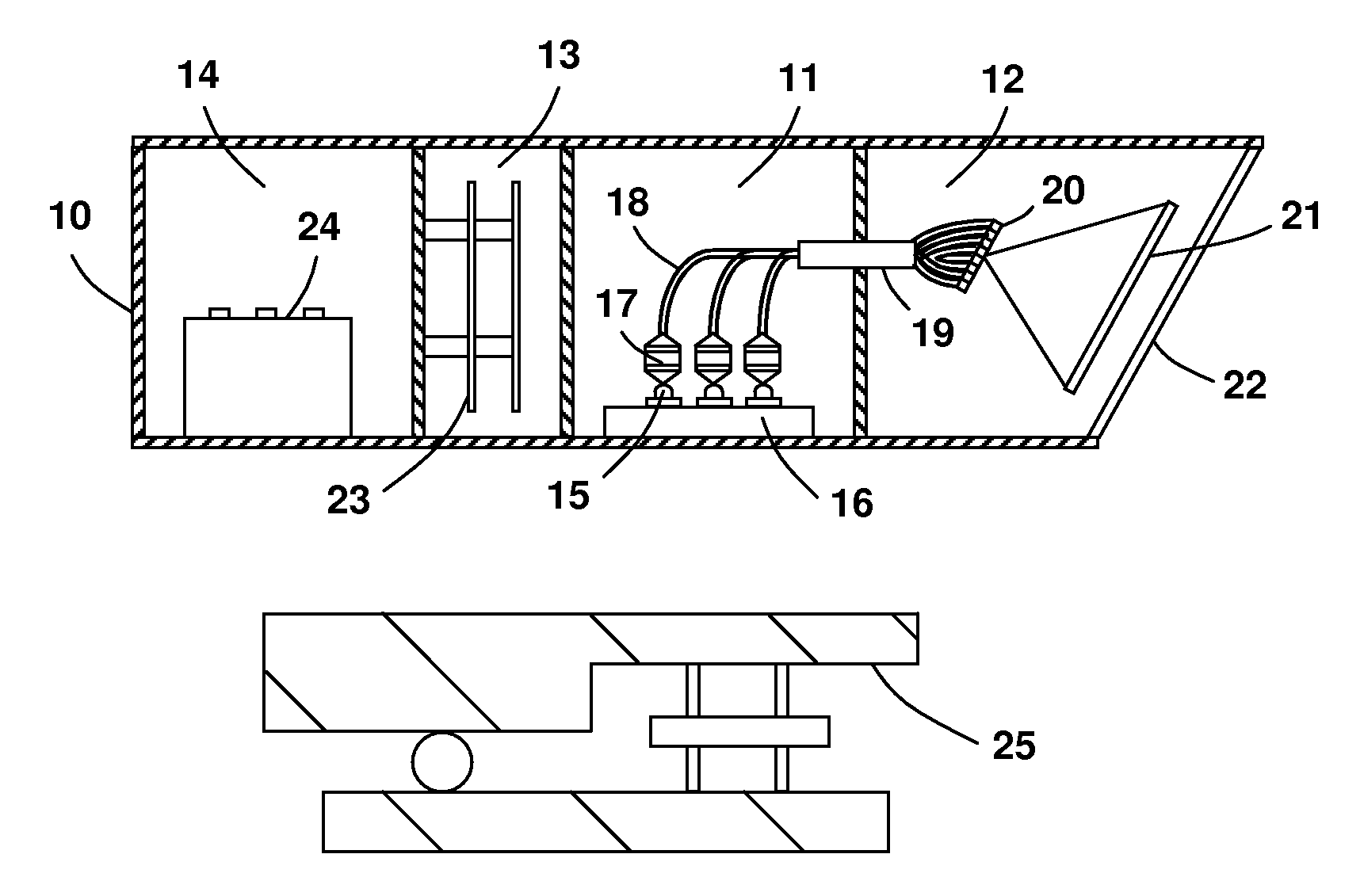
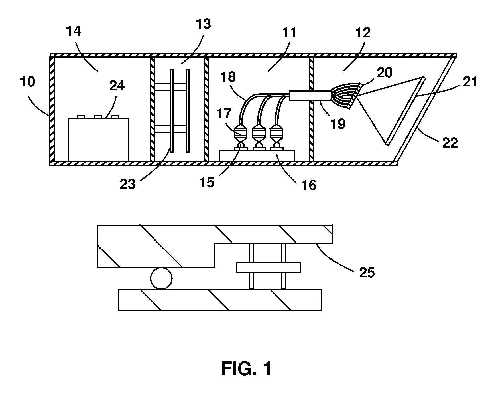
[0009] It is thus the overall goal of the current invention to provide an LED based projection lighting apparatus that produce a high illuminance level and a large projection range, which meet the requirements for marking and demarcation enhancement in airports, waterways, and industrial environments.
[0010] In the present invention, the optical pattern is generated by a fiber array instead of a display device. Thus the total luminous flux of the optical pattern is no longer limited by the size of the display device. In addition, the high lumen loss induced by the incorporation of a display device is avoided. The LED to fiber coupling stage is also designed to achieve a high light coupling efficiency.
[0012] The high intensity LEDs employed in the present invention adopt a chip-on-board (COB) packaging configuration, where the LED chips are directly surface mounted on a thermal conductive substrate for improved heat dissipation. The COB package allows larger light emitting surface and higher drive current for the LED chip to increase its output power. The COB packaging also leads to long lifespan or lifetime, as well as wavelength and intensity stability. The optical fibers are designed to have a suitable numerical aperture (NA) and a core diameter to match with the divergence angle and size of the LED light beam so that a high coupling efficiency can be achieved.

Problems solved by technology

The display device, such as the DMD or LCD chip used in the Parker patent, has a very limited size.
Thus the optical pattern generated by the display device has a limited total luminous flux under LED illumination.
In addition, a high lumen loss occurs when the light is delivered from the LED array to the display device due to the relative large divergence angle of the LED light.
Therefore the illuminance level and projection range provided by the disclosed multimedia projector are not sufficient for marking and demarcation applications in airports, waterways, and industrial environments.

Method used


Image

  • Projection lighting apparatus for marking and demarcation
  • Projection lighting apparatus for marking and demarcation
  • Projection lighting apparatus for marking and demarcation

Examples


Embodiment Construction

[0018] Before describing in detail embodiments that are in accordance with the present invention, it should be observed that the embodiments reside primarily in combinations of method steps and apparatus components related to a projection lighting apparatus utilizing high intensity LEDs. Accordingly, the apparatus components and method steps have been represented where appropriate by conventional symbols in the drawings, showing only those specific details that are pertinent to understanding the embodiments of the present invention so as not to obscure the disclosure with details that will be readily apparent to those of ordinary skill in the art having the benefit of the description herein.

[0019] In this document, relational terms such as first and second, top and bottom, and the like may be used solely to distinguish one entity or action from another entity or action without necessarily requiring or implying any actual such relationship or order between such entities or actions. ...


PUM


Abstract

A projection lighting apparatus is disclosed for marking and demarcation applications in airports, waterways, and industrial environments. The lighting apparatus comprises a plurality of high intensity LEDs with their output coupled to the input ends of a plurality of optical fibers. The output ends of the optical fibers are packaged to form a desired illumination pattern. The illumination pattern is projected onto the target surface through a secondary optical system for marking and demarcation enhancement.

Description

REFERENCE TO RELATED APPLICATIONS [0001] This application claims an invention which was disclosed in Provisional Patent Application No. 60 / 597,515, filed Dec. 7, 2005, entitled “Projection Lighting Apparatus Utilizing High Intensity LEDs”. The benefit under 35 USC § 119(e) of the above mentioned United States Provisional Applications is hereby claimed, and the aforementioned application is hereby incorporated herein by reference.FIELD OF THE INVENTION [0002] This invention generally relates to a lighting apparatus and more specifically to a projection lighting apparatus utilizing high intensity LEDs for marking and demarcation enhancement. BACKGROUND [0003] Optical pattern projection apparatus are widely employed in airports, waterways, and industrial environments for traffic control, incursion prevention, etc. It generally comprises a light source to provide illumination and a secondary optical system to project the light from the light source to a target surface to form the desire...

Claims


Application Information

Patent Timeline
IPC IPC(8): G02B6/32G02B6/42
CPCG02B6/4204H04N9/315
Inventor WANG, SEAN XIAOLUTIAN, RONGSHENG
Owner BWT PROPERTY
Learn More