
Method and Apparatus for Ear Canal Surface Modeling Using Optical Coherence Tomography Imaging

a technology of optical coherence tomography and ear canal, applied in tomography, applications, catheters, etc., can solve the problems of affecting the patient's hearing, so as to avoid the cost of previous direct scanning techniques

Active Publication Date: 2007-06-07
SIEMENS CORP
View PDF19 Cites 65 Cited by
  • Summary
  • Abstract
  • Description
  • Claims
  • Application Information

AI Technical Summary

Benefits of technology

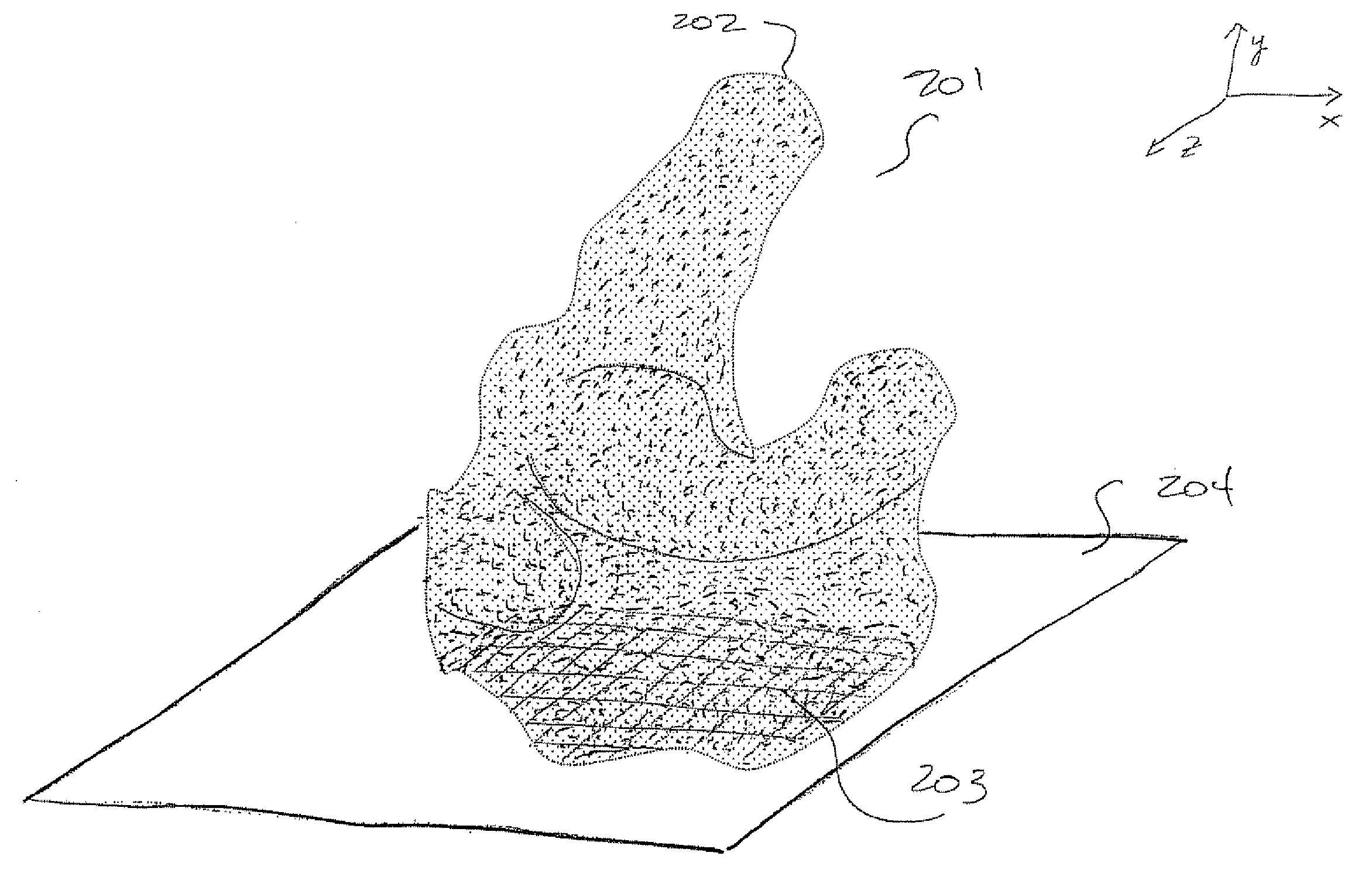
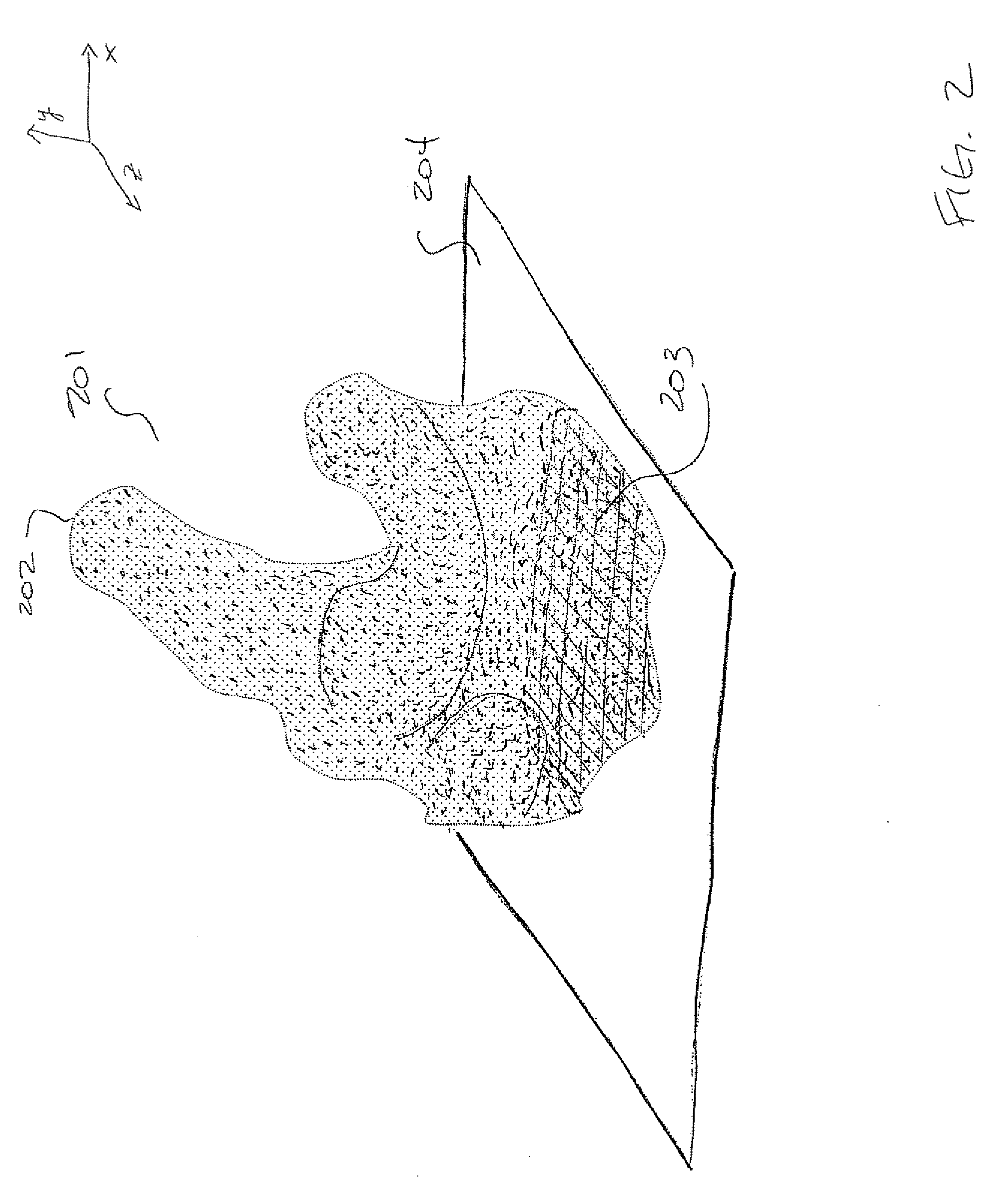
[0008] Accordingly, the present inventors have invented an improved method of designing hearing aid shells whereby an ear canal of a patient is directly imaged using a medical imaging technology, known as optical coherence tomography (OCT), that is functionally similar to well-known ultrasound techniques, yet relies on infrared light waves instead of sound. In a first embodiment, an OCT imaging sensor is inserted into an ear canal of a patient to a predetermined position. Then, a cross-section image of the ear canal is taken by, for example, rotating the OCT imaging sensor about a predetermined axis. Then, the OCT imaging sensor is moved to another location and another cross section image is taken. This process continues until a desired number of cross section images are obtained. In accordance with another embodiment, a contour line is then identified in each of the cross section images and a flow algorithm is used to identify the boundary of the ear canal cross section. Once the boundaries of each cross section have been identified, all of the cross section images are combined to generate a three dimensional image of the ear canal. In this way, the undesirable deformations caused by previous attempts of manually obtaining an ear impression and digitizing that impression and the expense of previous direct scanning techniques can be avoided.

Problems solved by technology

The present inventors have recognized that, while the aforementioned methods for designing hearing aid shells are advantageous in many regards, they are also disadvantageous in some aspects.
Accordingly, in transit, the impression could be damaged or could expand, shrink, or distort, due to external forces, temperature, or humidity to which the ear impression was exposed.
As a result, any resulting hearing aid produced using the deformed impression would not fit the patient properly.
Directly scanning the patient's ear without forming an impression could avoid the potential for a deformed ear impression, however previous techniques for conducting such scanning, such as computed tomography (CT) and / or magnetic resonance imaging (MRI) scans are prohibitively expensive.

Method used


Image

  • Method and Apparatus for Ear Canal Surface Modeling Using Optical Coherence Tomography Imaging
  • Method and Apparatus for Ear Canal Surface Modeling Using Optical Coherence Tomography Imaging
  • Method and Apparatus for Ear Canal Surface Modeling Using Optical Coherence Tomography Imaging

Examples


Embodiment Construction

[0020] As discussed above, the present inventors have recognized that using an ear impression mold to manufacture a hearing aid shell can be disadvantageous in some regards. In particular, as also discussed above, once an ear impression has been taken, it is subject to various external forces (e.g., temperature, humidity, etc) that may cause the impression to deform. Thus, any resulting hearing aid shell will not accurately reflect the true contours of the ear of which the impression was taken. Even when the ear impression is digitized (for example via laser scanning of the impression), inaccuracies in the ear impression may cause corresponding inaccuracies in a hearing aid shell. Therefore, the present inventors have recognized that it would be desirable to be able to directly measure the contours of an ear without manually taking a hearing aid impression of the ear. However, direct scanning of the human ear canal can be challenging due to, for example, the geometric complexity and...


PUM


Abstract

A method and apparatus for generating a three dimensional representation of an ear canal are disclosed whereby an ear canal of a patient is imaged using optical coherence tomography (OCT). In a first embodiment, cross-section images of an ear canal are taken by, for example, rotating an OCT imaging sensor about a predetermined axis at each of a plurality of positions. In accordance with another embodiment, a contour line is then identified in each of the cross section images and a flow algorithm is used to identify the boundary of the ear canal cross section. Once the boundaries of each cross section have been identified, all of the cross section images are combined to generate a three dimensional image of the ear canal.

Description

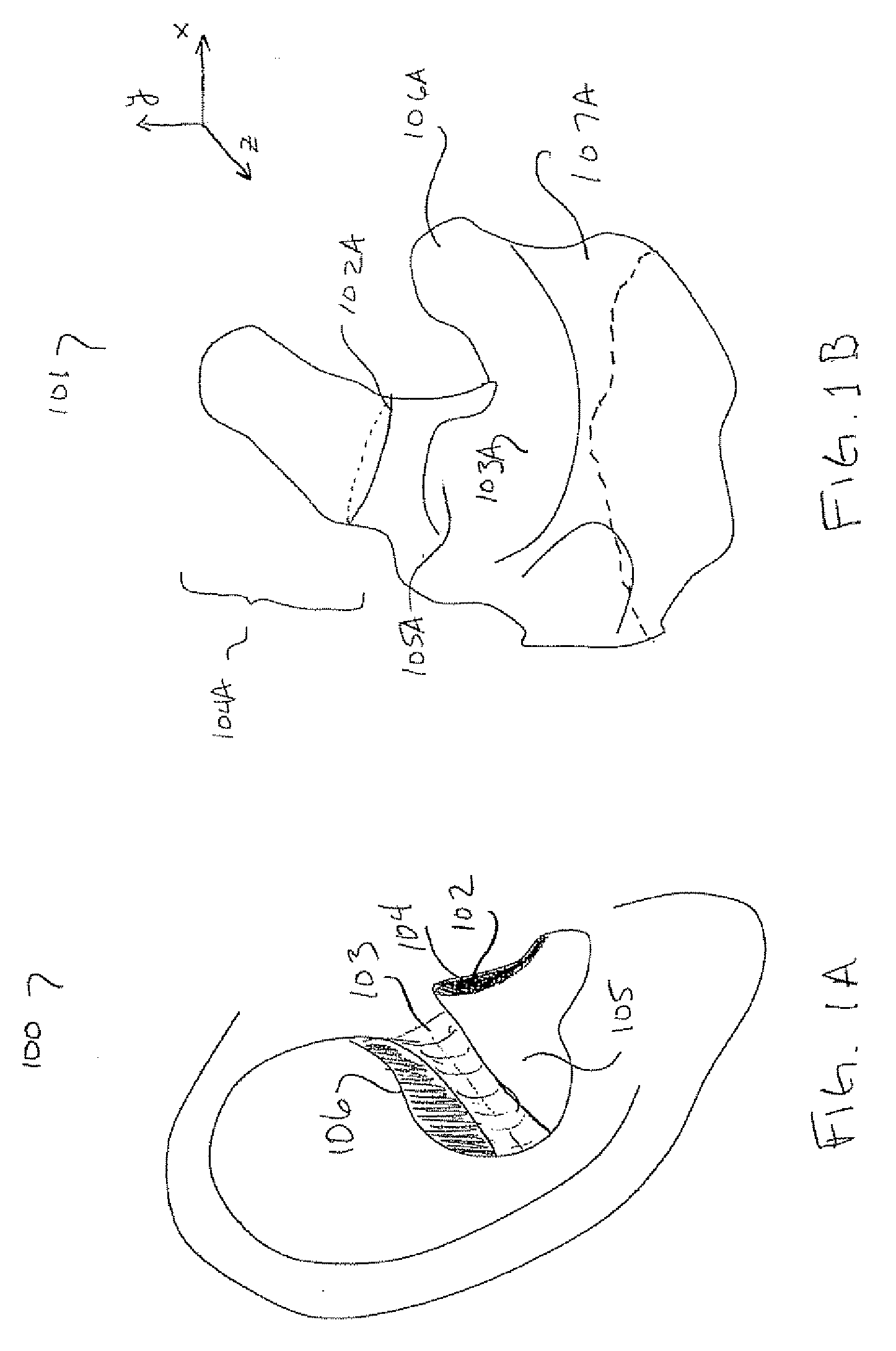
[0001] This patent application claims the benefit of U.S. Provisional Application No. 60 / 742,969, filed Dec. 7, 2005, which is hereby incorporated by reference herein in its entirety.BACKGROUND OF THE INVENTION [0002] The present invention relates generally to modeling the surface of three-dimensional objects and, more particularly, to modeling the surface of a human ear canal. [0003] The manufacturing of medical devices designed to conform to anatomical shapes, such as hearing aids, has traditionally been a manually intensive process due to the complexity of the shape of the devices. FIG. 1A shows a diagram of a human ear that is, for example, the ear of a patient requiring a hearing aid. Specifically, ear 100 has various identifiable parts such as, for example, aperture 102, crus 103, canal 104, concha 105 and cymba 106. As one skilled in the art will recognize, in order to produce a hearing aid for the patient, an ear impression is typically taken. Various processes for taking su...

Claims


Application Information

Patent Timeline
IPC IPC(8): H04R25/00
CPCH04R25/652H04R25/658A61B5/0066A61B5/1076A61B5/1077A61B5/6817
Inventor SLABAUGH, GREGORY G.TYAN, JASON JENN-KWEI
Owner SIEMENS CORP
Learn More