
Apparatus at a flat card or roller card for grinding a clothing drawn onto a rotating roller, having a carrying device

a technology of clothing and rollers, which is applied in the direction of grinding machines, grinding machine components, textiles and papermaking, etc., can solve the problems of having to adjust the grinding arrangement, the clothing is worn, and the equipment is not suitable for use, so as to achieve the effect of reducing the time and reducing the expenditure of apparatus

Inactive Publication Date: 2007-06-07
TRUETZSCHLER GMBH & CO KG
View PDF16 Cites 7 Cited by
  • Summary
  • Abstract
  • Description
  • Claims
  • Application Information

AI Technical Summary

Benefits of technology

[0009] As a result of the fact that the roller clothing is associated with the carrier having the at least one grinding element, instead of with a cover element or work element, the outlay in terms of apparatus and the time outlay required for service-readiness are substantially reduced. As a result of replacing a stationary cover element or work element by the carrier having the grinding element, arrangement and removal of the grinding device can be carried out in a short time by simple means. A particular advantage is provided by the fact that the dimensions over the length and width of the carrier and cover element or work element are the same or substantially the same. This allows replacement of the grinding device by a cover element or work element on the same flat card as well as mobile use on another flat card.

Problems solved by technology

In operation of the above-described wires, considerable wear of the fibre-processing clothing takes place.
In addition, contaminants can gather in the region of that clothing.
The latter-described problem especially comes to the fore when processing synthetic fibres, in the course of which the fibres can melt and stick to the clothing.
It is disadvantageous that the grinding arrangement has to be adjusted in an additional preparatory step, for which the grinding element is firstly set against the non-rotating clothing.
In addition, for adjustment of the biasing device, additional outlay in terms of apparatus is required.
It is furthermore disadvantageous that, in the case of mobile use or replacement of the apparatus, the time-consuming adjustment procedure is additionally required.

Method used


Image

  • Apparatus at a flat card or roller card for grinding a clothing drawn onto a rotating roller, having a carrying device
  • Apparatus at a flat card or roller card for grinding a clothing drawn onto a rotating roller, having a carrying device
  • Apparatus at a flat card or roller card for grinding a clothing drawn onto a rotating roller, having a carrying device

Examples


Embodiment Construction

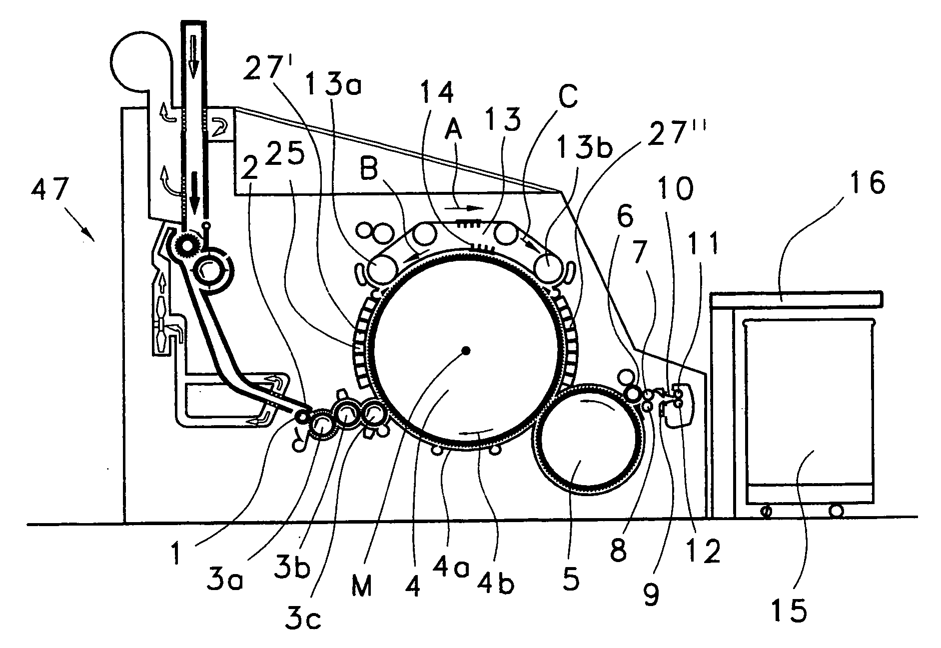
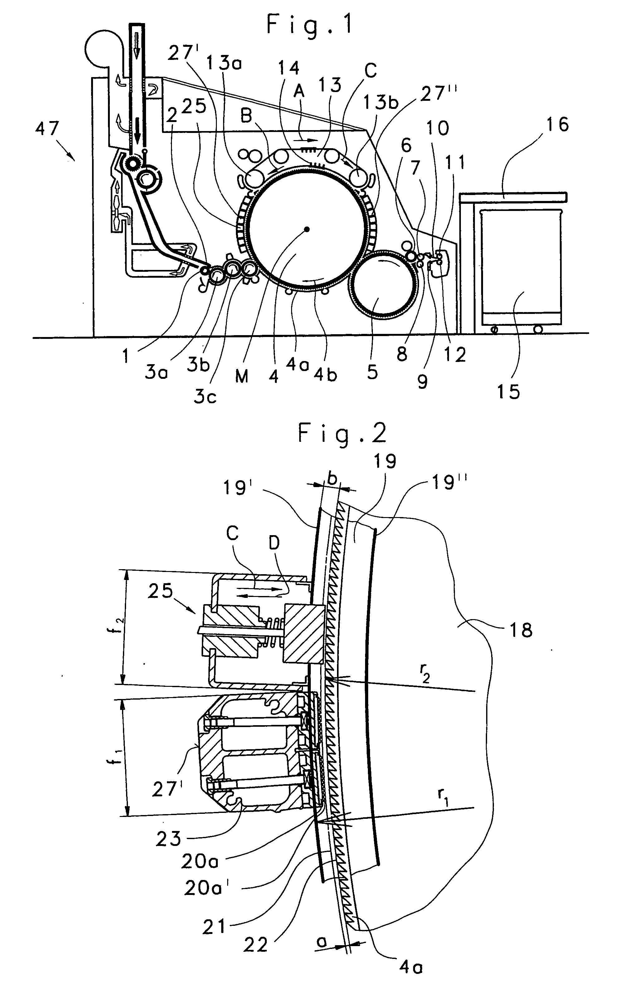
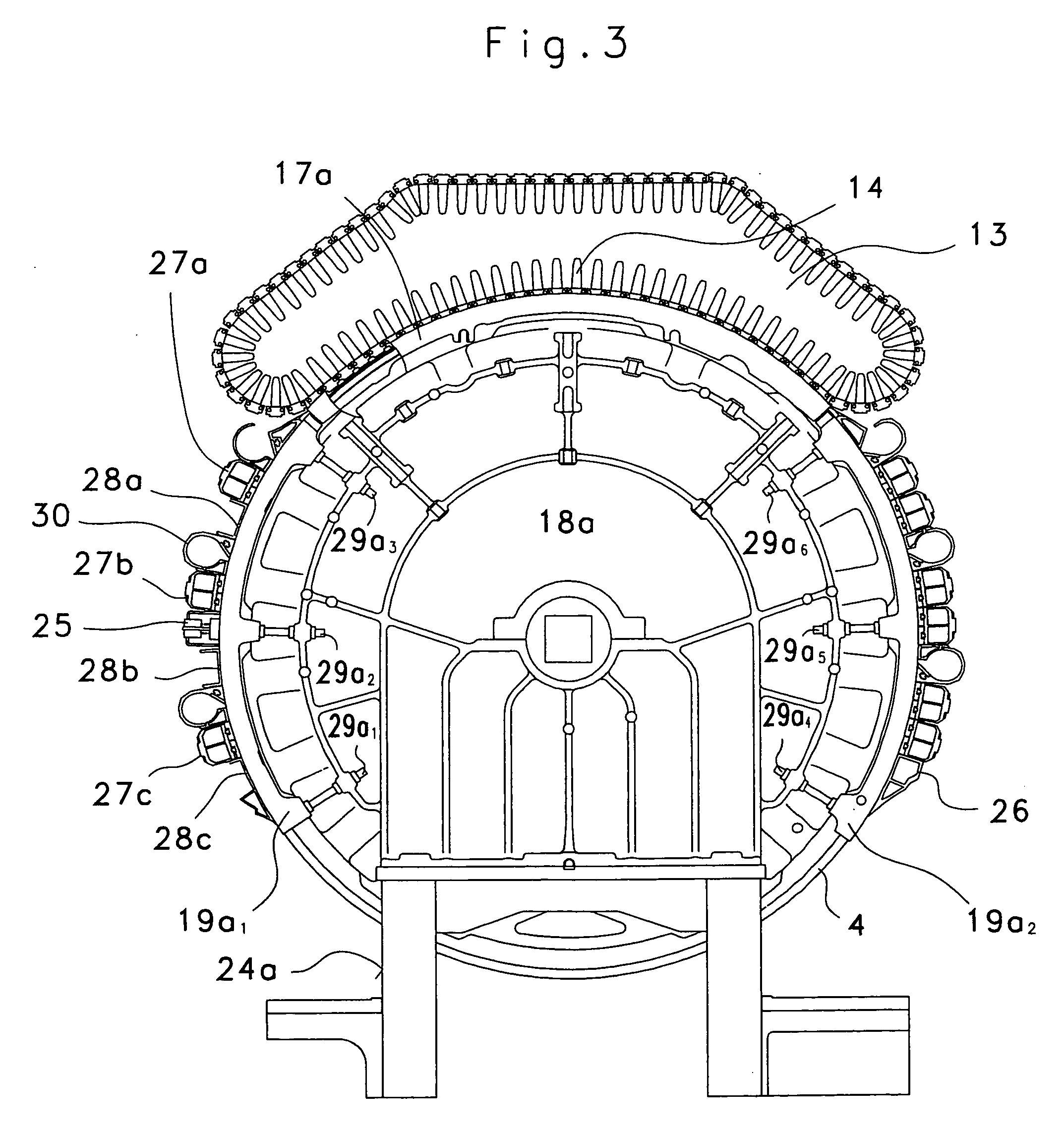
[0028]FIG. 1 shows a flat card, for example a TC 03 (Trade Mark) flat card made by Trützschler GmbH & Co. KG of Mönchengladbach, Germany, having a feed roller 1, feed table 2, lickers-in 3a, 3b, 3c, cylinder 4, doffer 5, stripper roller 6, nip rollers 7, 8, web-guiding element 9, web funnel 10, delivery rollers 11, 12, revolving card top 13 having card top guide rollers 13a, 13b and flats 14, can 15 and can coiler 16. The directions of rotation of the rollers are indicated by curved arrows. Reference letter M denotes the centre (axis) of the cylinder 4. Reference numeral 4a denotes the clothing and reference numeral 4b the direction of rotation of the cylinder 4. Reference letter B denotes the direction of rotation of the revolving card top 13 in the carding position and reference letter C denotes the return transport direction of the flats 14. Between the licker-in 3c and the back card top guide roller 13a there are arranged immobile cover elements or work elements, for example fix...


PUM

PropertyMeasurementUnit
widthaaaaaaaaaa
widthaaaaaaaaaa
displacementaaaaaaaaaa

Abstract

In an apparatus at a carding machine for grinding a clothing drawn onto a rotating roller, having a carrying device with at least one grinding element, the carrying device is attached to the carding machine. In order to make it possible, by means that are simple in terms of construction and installation, to reduce the preparation time, the grinding device with the at least one grinding element is interchangeable with one of a plurality of cover elements and / or work elements associated with the roller.

Description

CROSS REFERENCE TO RELATED APPLICATION [0001] This application claims priority from German Patent Application No. 10 2005 055 915.8 dated Nov. 22, 2005, the entire disclosure of which is incorporated by reference. BACKGROUND OF THE INVENTION [0002] The invention relates to an apparatus at a flat card or roller card for grinding a clothing drawn onto a rotating roller. Some grinding devices have a carrying device with at least one grinding element and an advancing device serving to set the grinding element against the clothing, the apparatus comprising a biasing device serving for automatically continuing to push forward the grinding element in a contact-making direction during the grinding procedure, and the carrying device being attached to the flat card or roller card. [0003] When textile fibres are processed, the fibres are oriented and cleaned with the aid of flat cards or roller cards. Those fibre-processing apparatuses comprise at least one roller having a wall in the shape of...

Claims


Application Information

Patent Timeline
Patent Type & Authority Applications(United States)
IPC IPC(8): B24B51/00
CPCB24B19/18D01G15/38D01G15/00
Inventor LEDER, ARMINPFERDMENGES, GERDSCHMITZ, THOMAS
Owner TRUETZSCHLER GMBH & CO KG
Learn More