Torsional vibration damper

a torsional vibration and damper technology, applied in the direction of fluid couplings, rotary clutches, gearing, etc., can solve the problems that the damping curve provided by a tdc can still prove insufficient, and achieve the effect of shortening the travel distance and reducing the stiffness of the first energy storage group

Active Publication Date: 2007-06-14
ZF FRIEDRICHSHAFEN AG
View PDF7 Cites 27 Cited by
  • Summary
  • Abstract
  • Description
  • Claims
  • Application Information

AI Technical Summary

Benefits of technology

[0012] In a preferred design of the torsional vibration damper it is ensured that a predetermined stiffness ratio is obtained between the first energy-storage devices of the two energy-storage groups. By configuring the first sections of the characteristic curves of the two energy-storage groups in such a way that they end at different torque values, the transition between the softer first energy-storage devices of the two characteristic curves to the harder second energy-storage devices of the two characteristic curves occurs without an inflection point or an area with a clearly perceptible discontinuity in the characteristic curve which represents the sum of the two original characteristic curves and which is therefore called the “summation characteristic curve”. This effect is especially advantageous when the torque present at the torsional vibration damper is of an order of magnitude which coincides with the end of at least one of the first sections of the characteristic curve and with the beginning of at least one of the second sections of the characteristic curve and when it changes over to the other section of this characteristic curve as the result of a small change in torque. The section of the characteristic curve active at the moment would change quite frequently in this way when a torsional vibration of alternating sign is superimposed on a torque of this order of magnitude. Through appropriate configuration of the characteristic curves, it is possible, either in addition or as an alternative, to ensure that the inflection point in question between the two sections of the characteristic curve is present in a partial load range relevant to fuel economy, this range usually being present when the throttle valve is at an opening angle in the range of 25-50%. With this type of design, the previously mentioned torsional vibrations cannot cause a change from one section of the characteristic curve to another.
[0013] In correspondence with another preferred design of the torsional vibration damper, it is possible to ensure that a predetermined stiffness ratio is obtained between exclusively identical energy-storage devices of preferably the first energy-storage group and the first energy-storage devices of preferably the second energy-storage group. It is advantageous for the first energy-storage group to be designed for a comparatively low stop torque, where this stop torque corresponds to only a fraction of the torque which can be supplied by a drive such as the crankshaft of an internal combustion engine. This means that, when the torque to be transmitted from the drive does not exceed this stop torque, both the first energy-storage group and the second energy-storage group are active, whereas, when the torque to be transmitted is above this value, only the second energy-storage group is active. The advantage of a design such as this is that the stiffness of the first energy-storage group can be made very low, because it does not have to absorb all of the torque which the drive can deliver. For this reason, the first energy-storage group is preferably located radially outside the takeoff-side energy-storage group, and in this way its springs acquire a longer travel distance.

Problems solved by technology

To the extent that the bridging clutch is to be closed even at speeds as low as 1,000 rpm, however, even the damping curve provided by a TDC can still prove insufficient.

Method used


Image

  • Torsional vibration damper
  • Torsional vibration damper
  • Torsional vibration damper

Examples


Embodiment Construction

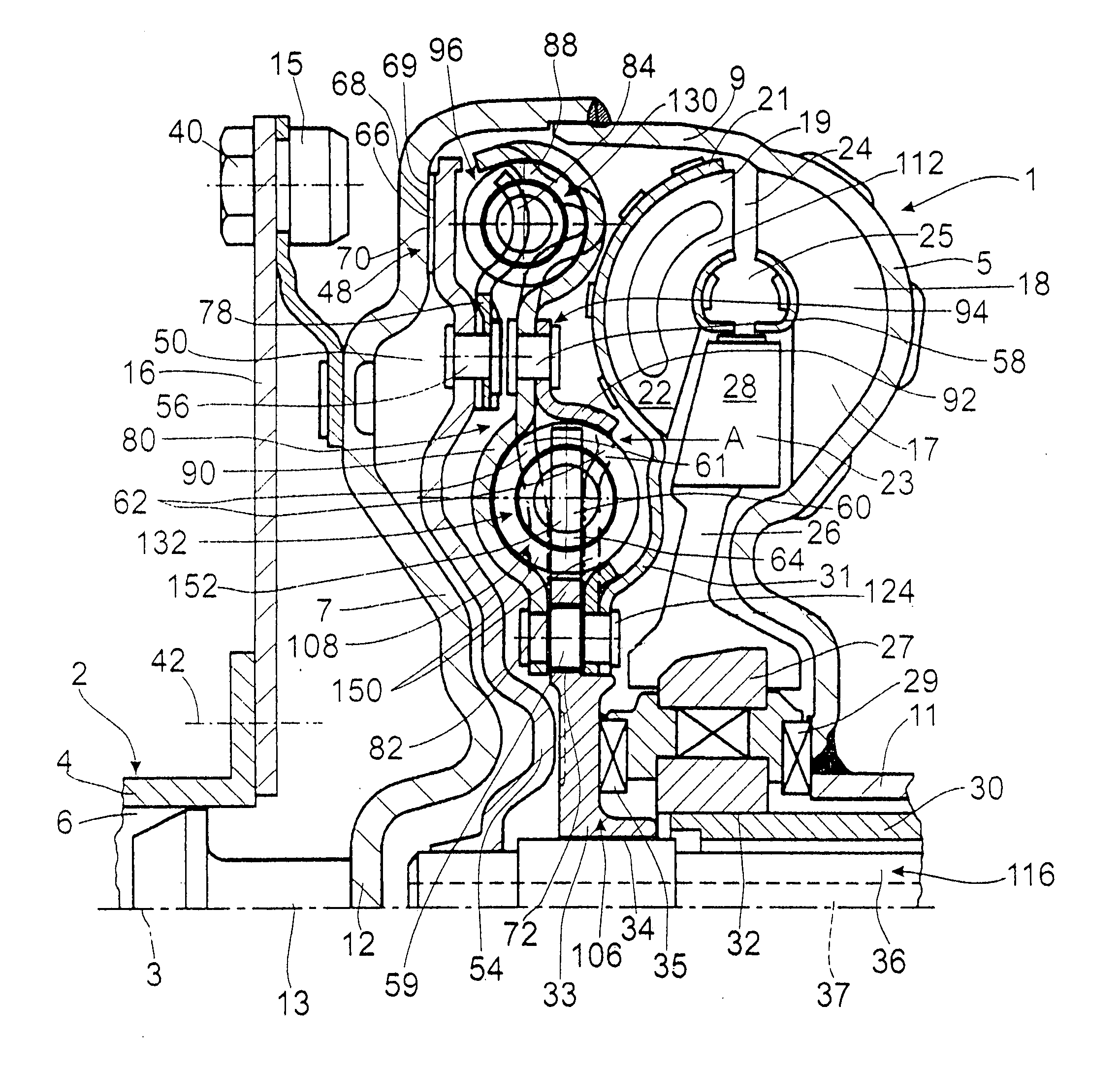
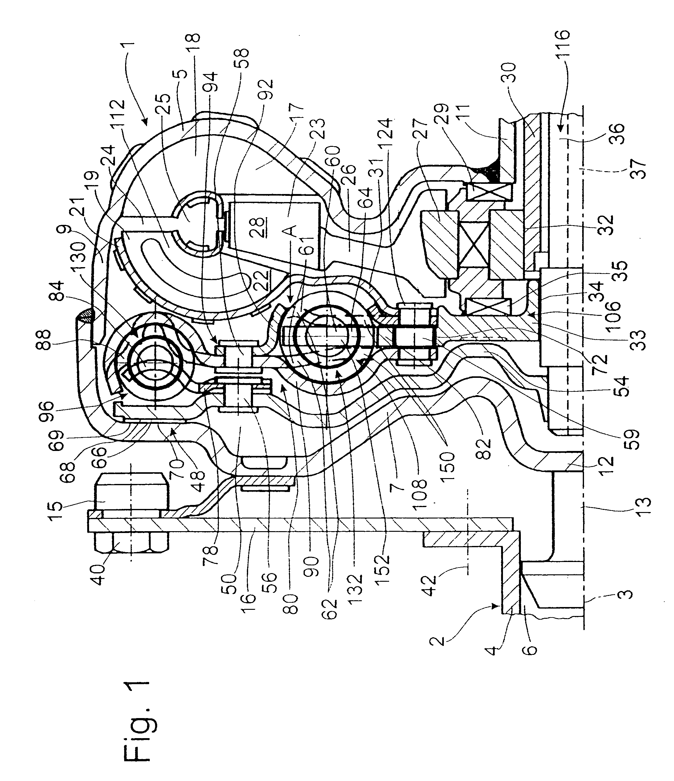
[0033]FIG. 1 shows a hydrodynamic clutch arrangement 1 in the form of a hydrodynamic torque converter, which is able to rotate around an axis of rotation 3. The hydrodynamic clutch arrangement 1 has a clutch housing 5, which, on the side facing a drive 2, such as the crankshaft 4 of an internal combustion engine, has a housing cover 7, which is permanently connected to a pump wheel shell 9. This shell 9 merges in its inner radial area with a pump wheel hub 11.

[0034] The housing cover 7 has in the radially inner area a journal hub 12 carrying a bearing journal 13. In a manner known, the bearing journal 13 is mounted in a recess 6 in the crankshaft 4 to center the clutch housing 5 on the drive side. The housing cover 7 also has a mounting receptacle 15, which is used to attach the clutch housing 5 to the drive 2, namely, by way of the flexplate 16. This flexplate 16 is attached to the mounting receptacle 15 by means of fastening elements 40 and to the crankshaft 4 by means of fasteni...


PUM


Abstract

A torsional vibration damper for a bridging clutch of a hydrodynamic clutch arrangement has a drive-side damping device, which can be brought into working connection with the housing of the clutch arrangement and is provided with a drive-side transmission element, which acts via a drive-side energy-storage group on an intermediate transmission element, and a takeoff-side damping device, which uses a takeoff-side group of energy-storage devices to establish a working connection between the intermediate transmission element and a takeoff-side transmission element, which is connected to a takeoff-side component of the hydrodynamic clutch arrangement. A predetermined stiffness ratio is obtained between the energy-storage devices of a first group and the energy-storage devices of a second group, and the energy-storage devices of the drive-side group have a stiffness different from that of the assigned energy-storage devices of the takeoff-side group.

Description

BACKGROUND OF THE INVENTION [0001] The invention pertains to a torsional vibration damper on a bridging clutch of a hydrodynamic clutch arrangement. [0002] A torsional vibration damper of this type is known from, for example, U.S. Pat. No. 7,073,646. The hydrodynamic clutch arrangement, realized in the form of a torque converter, is designed with a bridging clutch. The side of the clutch piston facing the clutch housing is provided with a friction surface, by means of which the piston can be brought into frictional connection by way of an intermediate plate with an opposing friction surface on the clutch housing. The bridging clutch establishes a working connection between the clutch housing, which is attached nonrotatably to a drive such as the crankshaft of an internal combustion engine, and the torsional vibration damper. That is, the connection is established between the clutch housing and a drive-side transmission element of the torsional vibration damper, this transmission ele...

Claims


Application Information

Patent Timeline
Patent Type & Authority Applications(United States)
IPC IPC(8): F16H45/02F16F15/123
CPCF16F15/12366F16H45/02F16H2045/007F16H2045/0226F16H2045/0231F16H2045/0247
Inventor WACK, ERWINSASSE, CHRISTOPHSUDAU, JORG
Owner ZF FRIEDRICHSHAFEN AG
Why Eureka
Try Eureka