Composite switch

a technology of composite switches and switches, applied in the direction of tumbler/rocker switches, snap-action arrangements, electrical apparatus, etc., can solve the problems of difficult suppression of noise generation, limit of shortening the tilting operation stroke, etc., to reduce the outer size, suppress noise generation, and miniaturize various electronic devices

Inactive Publication Date: 2007-06-14
PANASONIC CORP
View PDF4 Cites 2 Cited by
  • Summary
  • Abstract
  • Description
  • Claims
  • Application Information

AI Technical Summary

Benefits of technology

[0027] When the operation body and the driving body are formed of an inelastic material, it is possible to realize a composite switch in which a tilting operation stroke is short, and noise generated when movable contact bends is small, that is, the generation of noise is suppressed.
[0028] Furthermore, according to the present invention, the two pairs of push switches have a circular shape and are disposed in a manner in which they are displaced from each other in a range of the one pair of push switches in a direction parallel to the swing center shaft of the case. Such a configuration can reduce the outer size in the tilting direction of the composite switch and contribute to miniaturization of various electronic devices.
[0029] Furthermore, according to the present invention, the two pairs of push switches are operated by a same operation force and a contact position of the operation body pressing an upper surface of the driving body at the time of tilting operation is a position displaced from the center between the pair of push switches at a lower side in the tilting direction. With such a configuration, it i

Problems solved by technology

However, in the above-mentioned conventional composite switch, since driving bodies 2B to 5B are formed of an elastic insulating material such as rubber, there is limitation to shortening the tilting operation strok

Method used


Image

  • Composite switch
  • Composite switch
  • Composite switch

Examples


embodiment

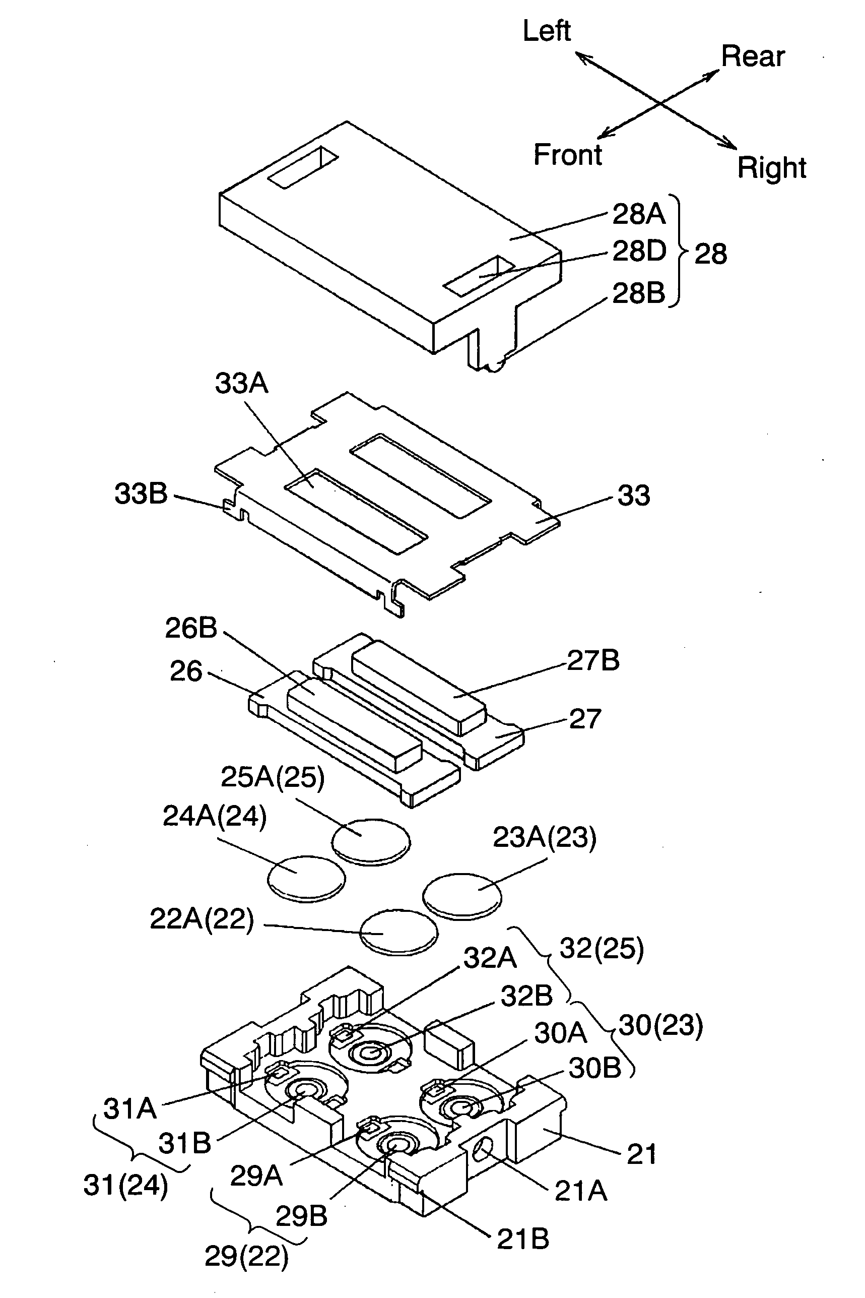
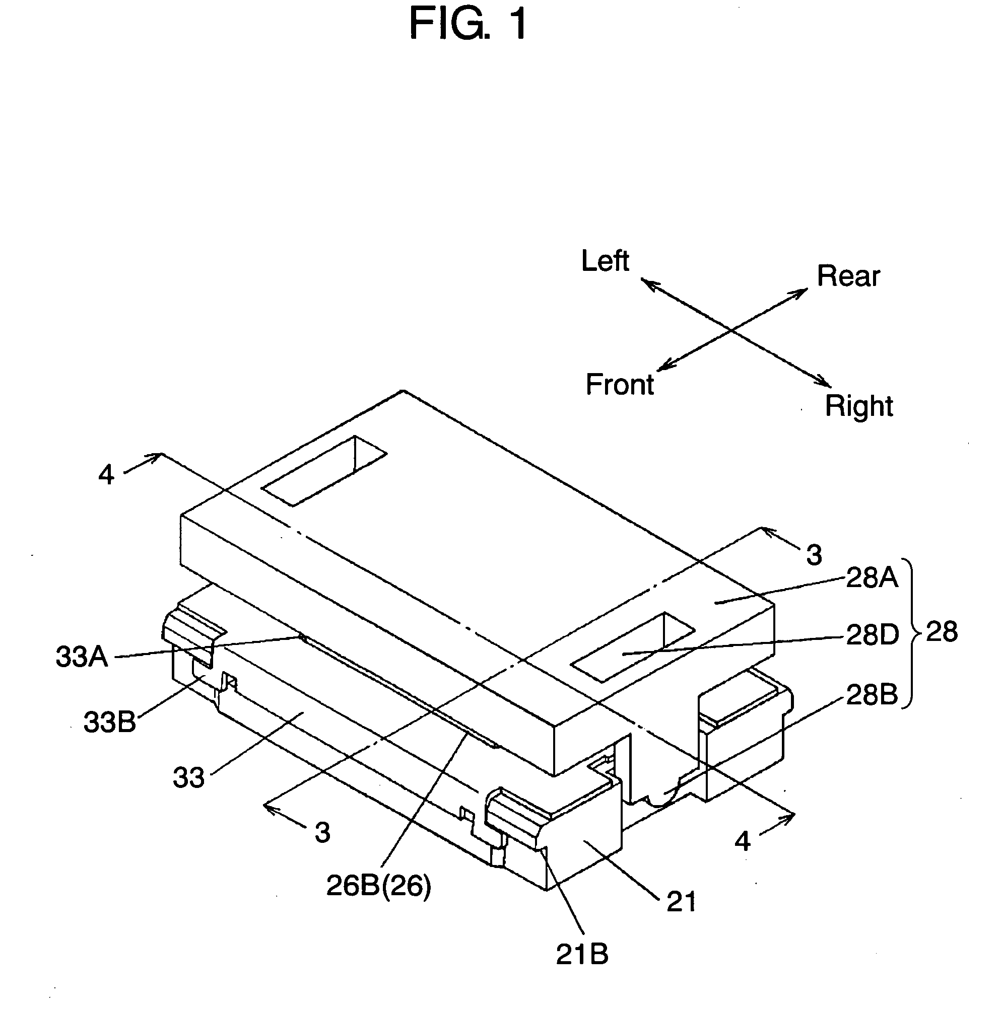
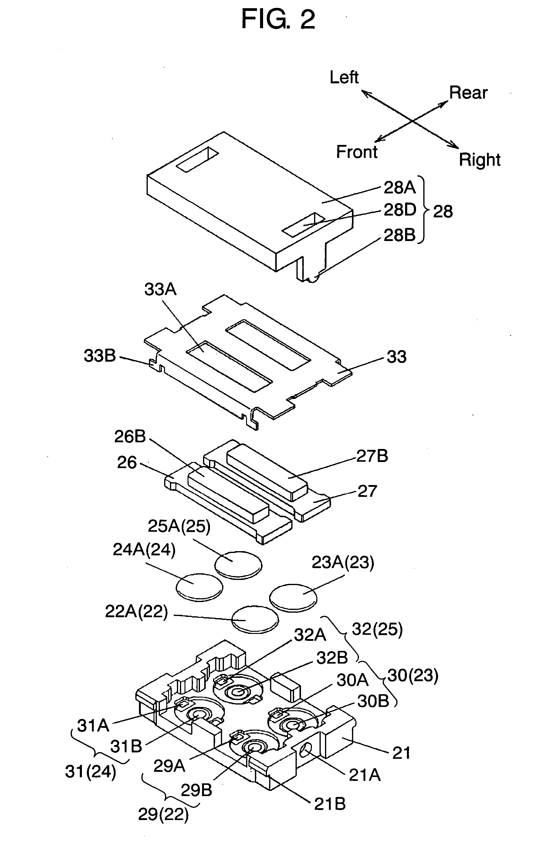
[0047]FIG. 1 is an external perspective view showing a composite switch in accordance with an embodiment of the present invention. FIG. 2 is an exploded perspective view showing a composite switch in accordance with an embodiment of the present invention. FIG. 3 is a sectional view taken along line 3-3 of FIG. 1. FIG. 4 is a sectional view taken along line 4-4 of FIG. 1. FIG. 5 is a plan view with an operation body and a cover being removed. FIG. 6 is a sectional view to illustrate an operation state of FIG. 4. FIG. 7 is a sectional view to illustrate an operation state of FIG. 4. FIG. 8 is a sectional view showing another embodiment in which a movable contact and an operation body are changed. FIG. 9 is a plan view showing another embodiment with an operation body and a cover being removed.

[0048] In FIGS. 1 and 2, case 21, made of an insulating resin, has a box-like shape that is square seen from the upper surface. In the vicinities of four corners on the bottom surface of case 21...


PUM


Abstract

A composite switch having a configuration in which: on the upper part of movable contacts of a first switch to a fourth switch disposed in a case, two driving bodies made of an inelastic insulating material such as polyamide are mounted in parallel to a swing center shaft; an upper surface of the case is covered with a cover having two long holes from which upper parts of the two driving bodies protrude; and the two driving bodies are pressed by an operation body, made of an inelastic insulating resin, which is swingably supported. With a composite switch having this configuration, an operation stroke is short and the generation of noise can be suppressed.

Description

BACKGROUND OF THE INVENTION [0001] 1. Field of the Invention [0002] The present invention relates to a composite switch that is used mainly in an input operation section, and the like, of a mobile communication device such as a portable telephone and a pager, and various kinds of small-sized and multifunctional electronic devices such as a remote control, an audio device, a game device, a car navigation system, and a digital camera, and operates in two stages by tilting operation of an operation section. [0003] 2. Background Art [0004] A conventional composite switch operating in two stages by tilting operation is described in FIG. 11 to FIG. 14. [0005]FIG. 11 is an external perspective view showing a conventional composite switch. FIG. 12 an exploded perspective view showing a conventional composite switch. FIG. 13 is a sectional view taken along line 13-13 of FIG. 11. FIG. 14 is a sectional view taken along line 14-14 of FIG. 11. [0006] In FIGS. 11 to 14, box-like case 1, made of ...

Claims


Application Information

Patent Timeline
IPC IPC(8): H01H21/00
CPCH01H5/30H01H23/003
Inventor YAMASAKI, MASATO
Owner PANASONIC CORP
Why Eureka
Try Eureka