Plate material packing box, plate material transporting method, and plate material loading or unloading method

a plate material and packing box technology, applied in the field of plate material packing boxes, can solve the problems of difficult storage in the airplane storage room, difficult storage, and limited weight to be transported by forklifts, and achieve the effect of preventing dust from entering the packing box and being easy to stor

Inactive Publication Date: 2007-06-14
ASAHI GLASS CO LTD
View PDF22 Cites 50 Cited by
  • Summary
  • Abstract
  • Description
  • Claims
  • Application Information

AI Technical Summary

Benefits of technology

[0010] The present invention has been made in view of the above-described situation, and it is an object of the present invention to provide a plate material packing box capable of preventing dust from entering into the packing box, easily storable in a storage room with a low c

Problems solved by technology

However, with this packing rack, the plate glass is transported in a standing state, and it sometimes happens that in the case of air transportation, the height dimension is so large (e.g. at least 2 m) that it cannot be smoothly stored in a storage room in an airplane.
However, in a clean room in which a production of display panels is carried out, the weight to be transportable by a forklift, is restricted.
Therefo

Method used


Image

  • Plate material packing box, plate material transporting method, and plate material loading or unloading method
  • Plate material packing box, plate material transporting method, and plate material loading or unloading method
  • Plate material packing box, plate material transporting method, and plate material loading or unloading method

Examples


Embodiment Construction

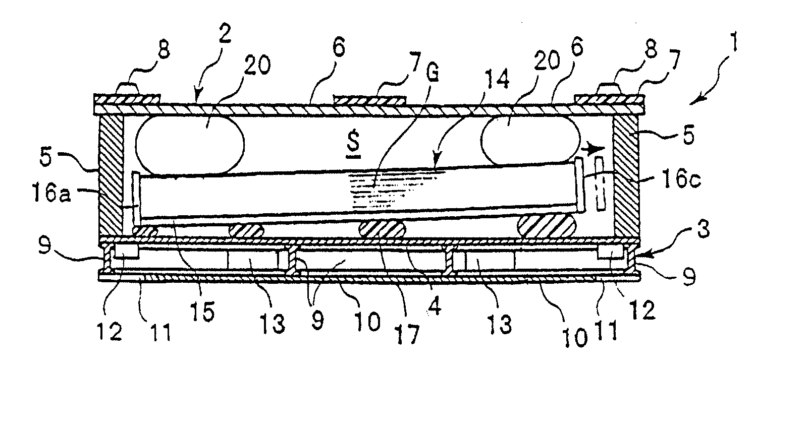
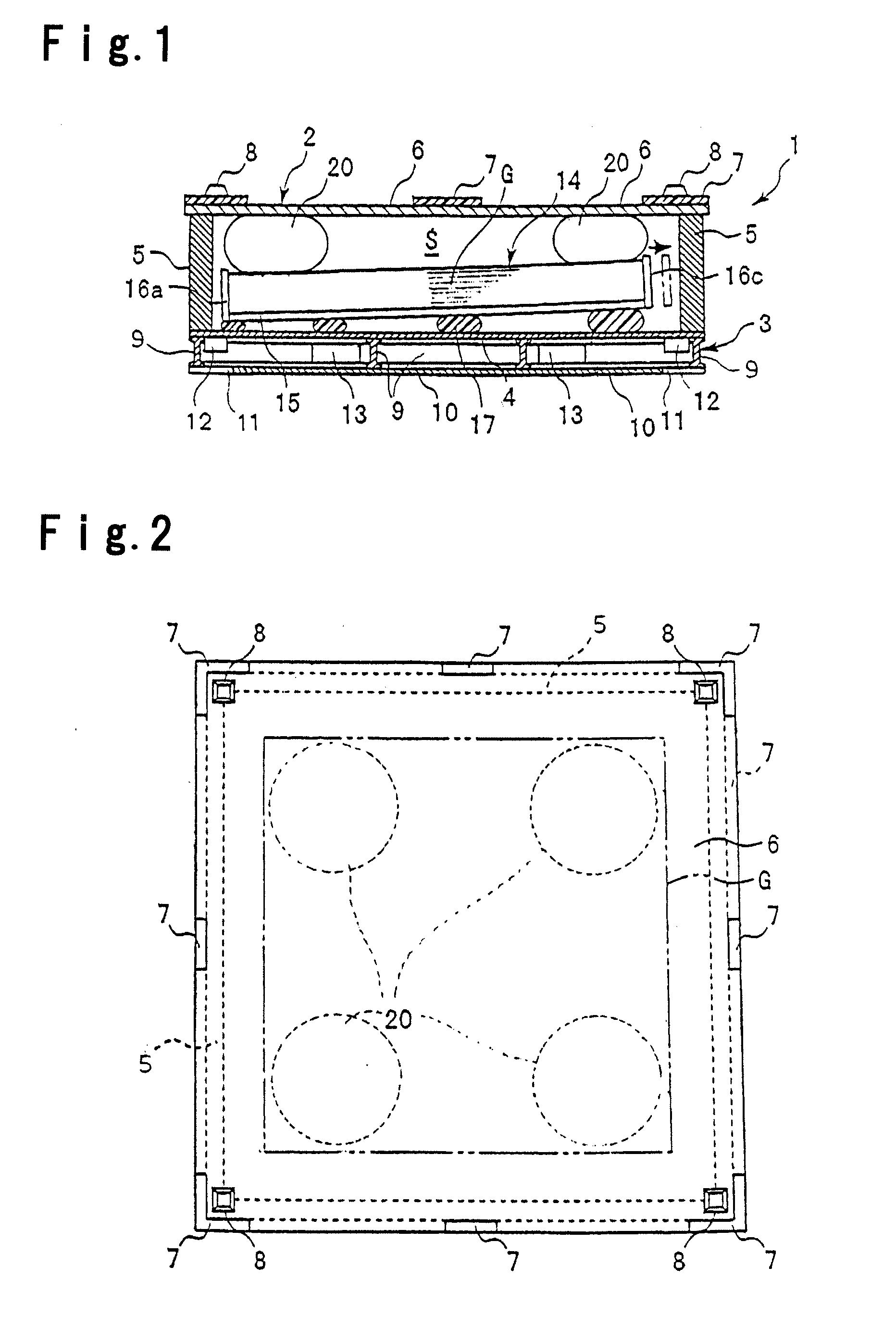
[0076]FIG. 1 is a vertical cross-sectional view of the plate material packing box of the present invention. This embodiment is one applied to large size plate glass as the plate material G. The plate material packing box (hereinafter referred to as the packing box) 1 is designed to store a plurality (for example, 50 sheets) of plate materials G in a substantially horizontally stacked state. The packing box 1 comprises a pedestal 3, an upper cover 2 put on the pedestal 3, and a plate material storage box 14 put on the pedestal 3 within this upper cover 2.

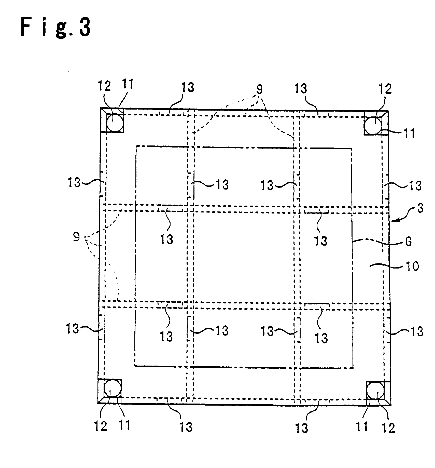
[0077] The pedestal 3 is one prepared in such a manner that a plurality of I-beam frame materials 9 formed by an extruded material made of e.g. an aluminum alloy are assembled lengthwise and crosswise in a lattice-like arrangement to form a frame, and on an upper side of this frame, an upper lining 4 is fixed, and on the lower side, a lower lining 10 is fixed.

[0078] A plate material storage box (hereinafter referred to as a storage...


PUM


Abstract

A plate material packing box capable of preventing dirt from entering thereinto, easily storable in a storage room with a low ceiling by reducing the height dimension during transportation, and capable of transporting plate materials efficiently and constantly; a plate material transporting method using such a plate material packing box; and a plate material loading or unloading method. The packing box comprises a pedestal 3 having an upper lining, a plate material storage box 14 put on the pedestal 3, and an upper cover 2 enclosing the plate material storage box 14 on the pedestal 3 and being detachable from the pedestal 3, wherein the plate material storage box 14 is an upwardly open support having a bottom plate 15 to have a plurality of plate materials G put thereon in a substantially horizontally stacked state, and side plate 16a to 16d along four sides of its periphery, the upper cover 2 is a downwardly open box having a top plate 6 covering the upper surface of the plate material storage box 14 and side frames 5 along four sides of its periphery; a vibration damper 17 is interposed between the pedestal 3 and the bottom plate 5; and a cushion material 20 is installed between the top plate 6 and the plate materials G put on the bottom plate 15.

Description

BACKGROUND OF THE INVENTION [0001] 1. Field of the Invention [0002] The present invention relates to a plate material packing box designed to pack plate materials, particularly large size plate materials for e.g. flat panel display (FPD) i.e. liquid crystal display or plasma display, or large size plate materials as intermediate products in the process for their production, and to be unpacked after the transportation; a plate material transporting method using such a plate material packing box; a plate material loading method; and a plate material unloading method. [0003] 2. Discussion of Background [0004] In recent years, there has been an increasing need for large size plate glass to be used for e.g. FPD glass. As a means to transport such large size plate glass, a packing rack is known wherein a plurality of plate glass are secured in a vertically standing state (e.g. Patent Document 1). [0005] However, with this packing rack, the plate glass is transported in a standing state, a...

Claims


Application Information

Patent Timeline
IPC IPC(8): B65D85/48B65D81/02
CPCB65D81/052B65D2519/0086
Inventor AOKI, KAZUHIRO
Owner ASAHI GLASS CO LTD
Why Eureka
Try Eureka