Color filter substrate and fabricating method thereof

a technology of color filter substrate and fabricating method, which is applied in the direction of photosensitive materials, instruments, transportation and packaging, etc., can solve the problems of narrow viewing angle, low aperture ratio, and inability to make the color filter substrate light and thin,

Active Publication Date: 2007-06-14
LG DISPLAY CO LTD
View PDF15 Cites 32 Cited by
  • Summary
  • Abstract
  • Description
  • Claims
  • Application Information

AI Technical Summary

Benefits of technology

[0025] To achieve these and other advantages and in accordance with the purpose of the present invention, as embodied and broadly described, a color filter substrate includes a substrate, a black matrix that defines cell areas on a substrate and prevents light leakage, a color filter formed in the cell areas defined by the black matrix, and a conductive thin film formed on the rear surface of the substrate for preventing the generation of static electricity, wherein the conductive thin film is formed of a photo-resist containing a conductive material.
[0026] In another aspect, a fabricating method of a color filter substrate includes forming a black matrix that defines cell areas on a substrate and prevents light leakag

Problems solved by technology

The vertical electric field type liquid crystal display device has an advantage in that the aperture ratio is high, but on the other hand, it also has a disadvantage in that the viewing angle is narrow, about 90°.
The horizontal electric field type liquid crystal display device has an advantage in that the viewing angle is wide, about 160°, but on the other hand, it also has a disadvantage in that the aperture ratio is low.
Further, in the case of forming the color filter s

Method used


Image

  • Color filter substrate and fabricating method thereof
  • Color filter substrate and fabricating method thereof
  • Color filter substrate and fabricating method thereof

Examples


Embodiment Construction

[0042] Reference will now be made in detail to the preferred embodiments of the present invention, examples of which are illustrated in the accompanying drawings.

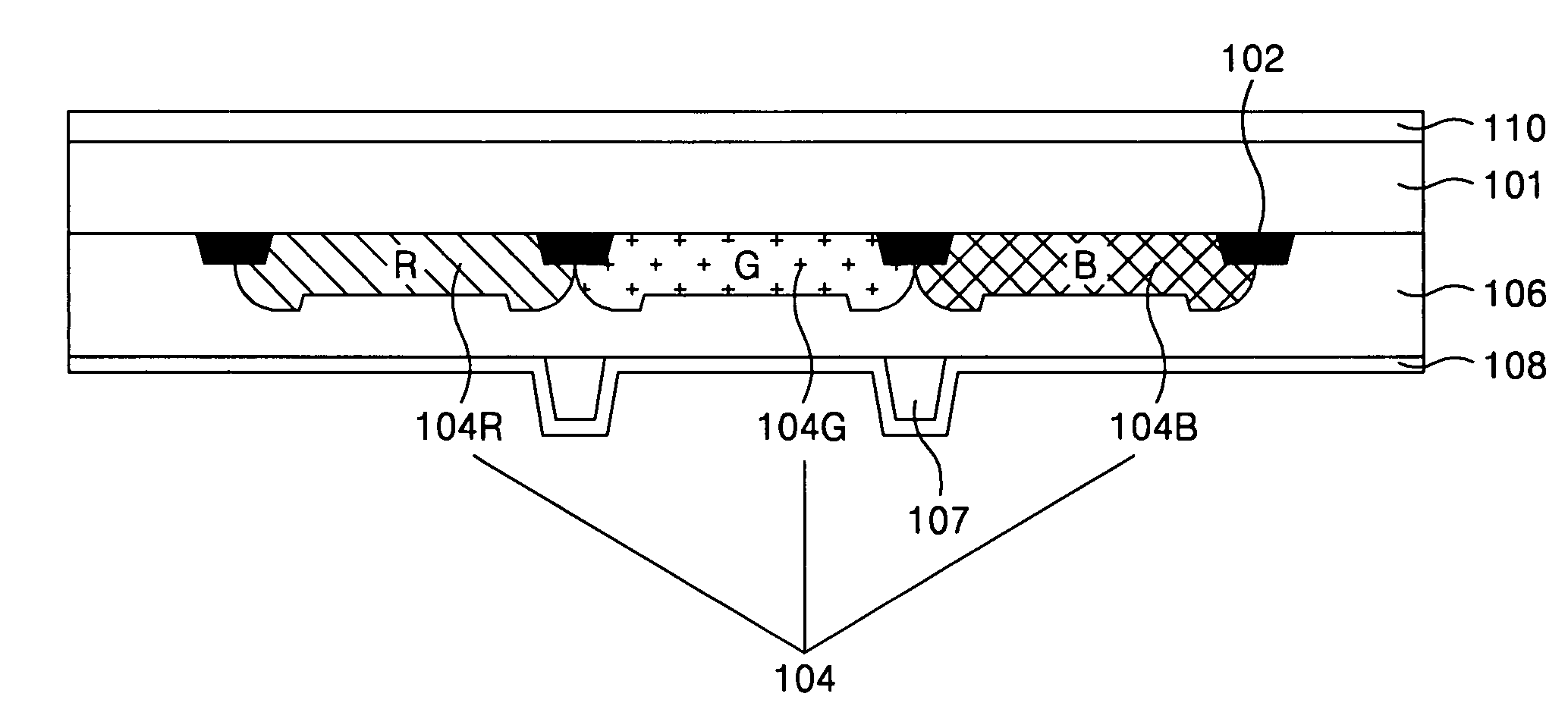
[0043]FIG. 3 is a plan view of a color filter substrate according to an embodiment of the present invention, and FIG. 4 is a cross-sectional view of the color filter substrate taken along the line I-I′ in FIG. 3. As shown in FIGS. 3 and 4, the color filter substrate according to the present invention includes a black matrix 102 formed on the substrate 101; color filters 104 formed in cell areas defined by the black matrix 102; an overcoat layer 106 which covers a step difference formed by the color filters 104 to form a planar surface; an alignment film 108 formed on the overcoat layer 106 to initially align liquid crystal molecules in a designated direction; and a conductive thin film 110 formed on the rear surface of the substrate 101 to prevent the generation of static electricity. A color filter substrate according to ...


PUM


Abstract

A color filter substrate includes a substrate, a black matrix that defines cell areas on a substrate and prevents light leakage, a color filter formed in the cell areas defined by the black matrix, and a conductive thin film formed on the rear surface of the substrate for preventing the generation of static electricity, wherein the conductive thin film is formed of a photo-resist containing a conductive material.

Description

[0001] This application claims the benefit of the Korean Patent Application No. P2005-0119956 filed on Dec. 8, 2005, which is hereby incorporated by reference in its entirety. BACKGROUND OF THE INVENTION [0002] 1. Field of the Invention [0003] The present invention relates to a component of a display device, and more particularly to a color filter substrate and a fabricating method thereof. Although the present invention is suitable for a wide scope of applications, it is particularly suitable for preventing static electricity on the color filter substrate. [0004] 2. Description of the Related Art [0005] In general, a liquid crystal display device controls the light transmittance of liquid crystal using an electric field across a layer of liquid crystal molecules between two substrates to display a picture. The liquid crystal display device uses cells in an active matrix in which a switching device is formed in each of the cells. Liquid crystal display devices are used as display in...

Claims


Application Information

Patent Timeline
IPC IPC(8): G02F1/1335H01L21/00H01L21/84
CPCB82Y20/00G02F1/133516G02F2202/16G02F2202/22Y10T428/1041H01L27/124Y10T428/1055Y10T428/1068G02F2202/36C09K2323/04C09K2323/053C09K2323/031G02F1/1335B82Y40/00
Inventor YOON, SANG SOON
Owner LG DISPLAY CO LTD
Why Eureka
Try Eureka