Light source assembly, and image display apparatus incorporating same

a technology of light source and image display, which is applied in the direction of optics, instruments, projectors, etc., can solve the problems of affecting the increase of the amount of light of a projector, the difficulty of increasing the number of condenser lenses, etc., and achieves efficient light direction, high volume utilization efficiency, and easy and inexpensive production.

Inactive Publication Date: 2007-06-14
MINEBEA CO LTD
View PDF6 Cites 17 Cited by
  • Summary
  • Abstract
  • Description
  • Claims
  • Application Information

AI Technical Summary

Benefits of technology

[0011] In the aspect of the present invention, the beam combining composite prism may be substantially a cube which has one surface thereof constituting the light outlet surface and remaining five surfaces thereof constituting the light inlet surfaces, and which includes four dichroic planes to transmit a light introduced from one of the five light inlet surfaces opposite to the light outlet surface and to selectively reflect and transmit lights introduced from four of the five inlet surfaces oriented orthogonal to the light outlet surface. Accordingly, the lights emitted from up to five point light sources can be duly combined by one beam combining composite prism without adjusting the optical axis. Thus, a high-intensity light source assembly with multiple point light sources can be easily and inexpensively produced while maintaining a high volume utilization efficiency, and also lights with respective different wavelengths emitted from plural point light sources can be appropriately combined into a light having a variety of spectrum distribution.
[0012] In the aspect of the present invention, a Fresnel lens may be disposed at the light inlet end and / or the light outlet end of the optical integrator. Accordingly, the spread angle of the light emitted from the optical integrator can be optimally controlled thereby efficiently guiding the light to an optical system, such as a light modulating means, disposed at the subsequent stage.
[0013] In the aspect of the present invention, the optical integrator may be a solid structure which is formed of a light transmissive material, and which provides a refractive index distribution with respect to the direction orthogonal to the optical axis of the optical integrator. Accordingly, the spread angle of the light emitted from the optical integrator can be optimally controlled.
[0014] According to another aspect of the present invention, there is provided a light source assembly including a plurality of light source units, each of which is defined by the light source assembly described above, and which are disposed parallel to one another. Since the light source assembly as the light source unit has a comparably simple structure where the beam combining composite prism and the optical integrator are coupled into one body, a high-intensity light source assembly with multiple point light sources can be readily and inexpensively produced without requirement to adjust the optical axes while maintaining a high volume utilization efficiency only by arranging plural light source units in parallel to one another.
[0015] According to still another aspect of the present invention, there is provided an image display apparatus which includes: any one of the light source assembles described above; a light modulating means to spatially modulate a light emitted from the light source assembly according to image information; and a projection optical system to magnify and project a light coming out from the light modulating means. Since the light source assembly incorporated in the image display apparatus is reduced in dimension and weight, the image display apparatus can be reduced in dimension and weight. Also, the lights emitted from the plurality of point light sources can be efficiently taken into the beam combining composite prism with an extremely small coupling loss, and multiple point light source can be readily arranged in the light source assembly. And, since the light source assembly allows the light intensity of the light source assembly to be easily controlled by changing the number of point light sources, the image display apparatus can be freely designed to incorporate an optimal light source assembly according to the required brightness of the image projected on the screen.
[0016] Thus, the light source assembly according to the present invention is reduced in dimension and weight, has function of multiplexing the lights from the plural point light sources and function of uniforming lights, and also achieves an enhanced light utilization efficiency. And, the image display apparatus of projection type according to the present invention, which incorporates the inventive light source assembly, can be reduced in dimension and weight and achieves an increased light intensity, which makes the image display apparatus suitable for, for example, a simple mobile projector powered by a battery.

Problems solved by technology

And, if the condenser lens 122 has a large aperture diameter for enhancing convergence efficiency of lights emitted from the LEDs 121, there arises a space constraint problem for housing the light source module 102, which makes it difficult to increase the number of the condenser lenses 122 and accordingly the number of the LEDs 121 consequently hampering the increase of the amount of light of a projector.

Method used


Image

  • Light source assembly, and image display apparatus incorporating same
  • Light source assembly, and image display apparatus incorporating same
  • Light source assembly, and image display apparatus incorporating same

Examples


first embodiment

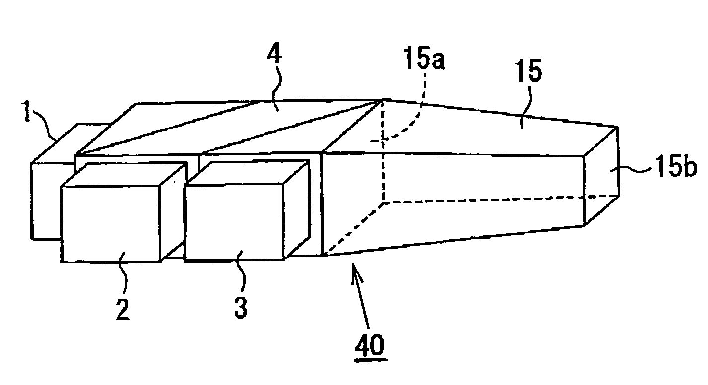
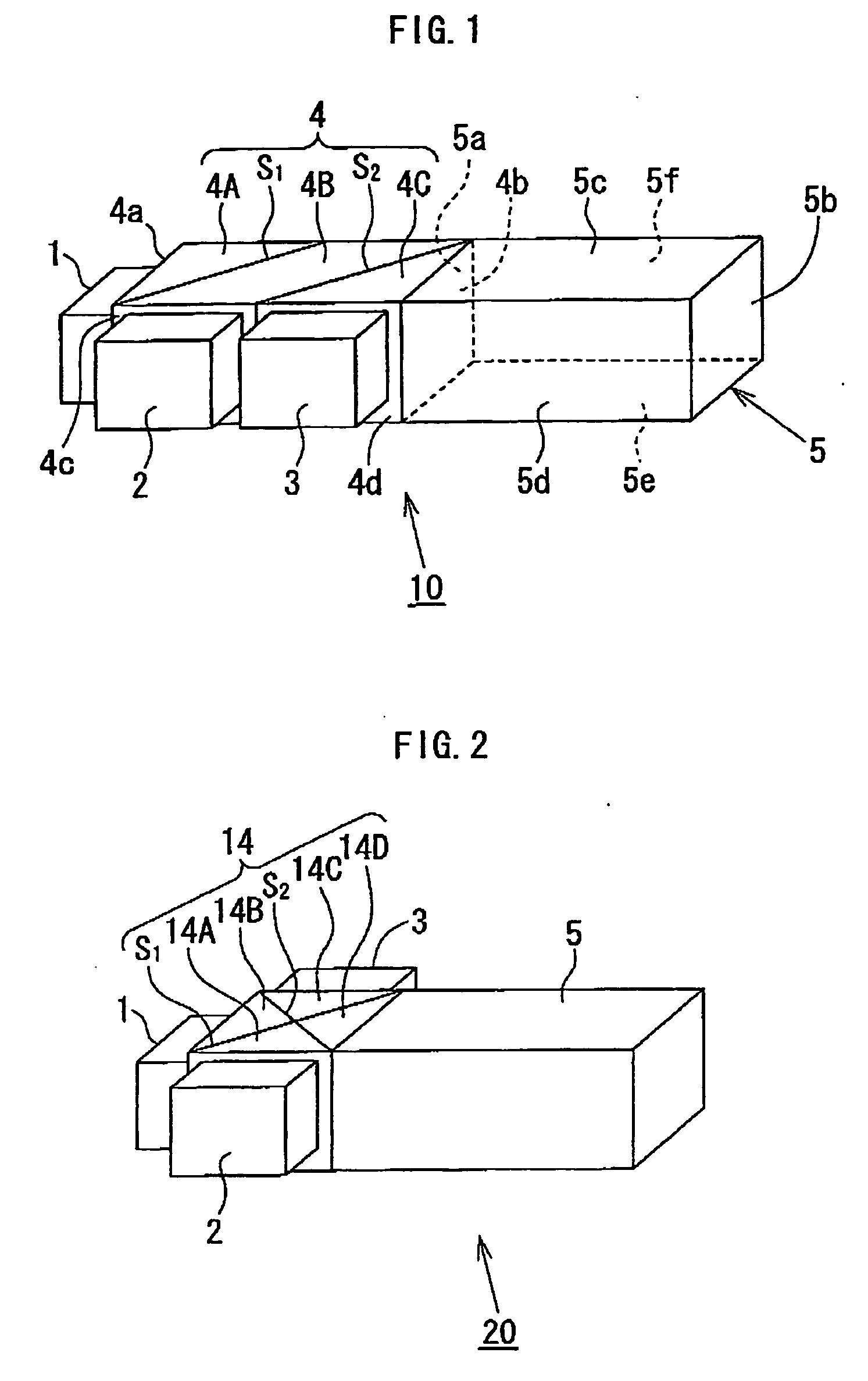
[0029] Referring to FIG. 1, a light source assembly 10 according to the present invention includes a plurality (three in the figure) of point light sources 1, 2 and 3, a beam combining composite prism 4, and an optical integrator 5.

[0030] In the present embodiment, the point light sources 1, 2 and 3 are LEDs and emit lights having respective different wavelengths: for example, the point light source 1 emits a light with a first wavelength (e.g., green), the point light source 2 emits a light with a second wavelength (e.g., blue), and the point light source 3 emits a light with a third wavelength (e.g., red).

[0031] The beam combining composite prism 4 is substantially a solid rectangular column composed of three optical prisms 4A, 4B and 4C, wherein surfaces 4a, 4c and 4d each constitute a light entrance (hereinafter referred to as light inlet surface(s) as appropriate), and a surface 4b constitutes a light exit (hereinafter referred to as light outlet surface as appropriate). A dic...

third embodiment

[0044] Referring to FIG. 6A, a light source assembly 50 according to the present invention is structured basically same as the light source assembly 10 of FIG. 10 but further includes a Fresnel lens 26 disposed at a light outlet end 5b of an optical integrator 5 (preferably fixedly coupled into a single structure by adhesive). The Fresnel lens 26 is structured such that a refraction pattern including a plurality of minute circles arranged concentrically is formed on a surface of a plate-like transparent substrate so as to represent a curvilinear surface of a lens (e.g., a convex lens). With this structure, the spread angle of a combined light emitted from the optical integrator 5 can be optimally controlled. In the light source assembly 50 of FIG. 6A, the plate-like Fresnal lens 26 can be easily put together with the optical integrator 5 into a single structure thus maintaining an advantageous structure of a small dimension with a small number of components and also efficiently guid...

fifth embodiment

[0053] the present invention, which refers to an image display apparatus, will hereinafter be explained with reference to FIG. 9. While FIG. 9 shows an image display apparatus incorporating the light source assembly 50 of FIG. 6A, the present invention is not limited to this arrangement, and any one of the light source assemblies described above may alternatively be used.

[0054] Referring to FIG. 9, an image display apparatus 90 includes the aforementioned light source assembly 50, a light modulating means 54 to spatially modulate a light emitted from the light source assembly 50 according to image information, and a projection optical system 56 to magnify and project a light coming out from the light modulating means 54.

[0055] The light modulating means 56 is, for example, a transmissive liquid crystal display (LCD) element adapted to control, pixel by pixel transmission and non-transmission of light according to image information sent from a driving circuit (not shown). The LCD el...


PUM


Abstract

A light source assembly includes: a plurality of point light sources; a beam composing composite prism including a plurality of light inlet surfaces, a plurality of dichroic planes, and a light outlet surface; and an optical integrator including a plurality of light reflecting planes forming a light guide path, a light inlet end corresponding to one end of the light guide path, and a light outlet end corresponding to the other end of the light guide path. In the light source assembly, the plurality of point sources are each disposed in contact with one light inlet surface of the beam combining composite prism, and the beam combining composite prism and the optical integrator are coupled to each other such that the light outlet surface of the beam combining composite prism and the light inlet end of the optical integrator are in contact with each other.

Description

BACKGROUND OF THE INVENTION [0001] 1. Field of the Invention [0002] The present invention relates generally to a light source assembly and an image display apparatus, and particularly to a light source assembly including a plurality of point light sources, and an image display apparatus incorporating such a light source assembly. [0003] 2. Description of the Related Art [0004] Conventionally, a discharge lamp, such as an ultrahigh-pressure mercury lamp, a metal halide lamp, a xenon lamp, and the like, has been used as a light source for a projection image display apparatus (hereinafter referred to as “projector” as appropriate), such as front projector, a rear production television, and the like. Meanwhile, recently, a projector has been developed in which light emitting diodes (LEDs) of red (R), green (G) and blue (B) color are used as a light source. Such a projector contributes to reducing its structural dimension and also reportedly performs a better color reproducibility than a...

Claims


Application Information

Patent Timeline
Patent Type & Authority Applications(United States)
IPC IPC(8): G03B21/00
CPCG03B21/208
Inventor KITAMURA, ATSUSHI
Owner MINEBEA CO LTD
Why Eureka
Try Eureka