DC-DC Converter for overvoltage protection

a converter and overvoltage protection technology, applied in the direction of electric variable regulation, process and machine control, instruments, etc., can solve the problems of primary control circuit b, power source voltage vsub>cc /sub>may rise and exceed the withstand voltage, etc., to reduce the input impedance, and reduce the effect of power input impedan

Active Publication Date: 2007-06-14
SANKEN ELECTRIC CO LTD
View PDF4 Cites 31 Cited by
  • Summary
  • Abstract
  • Description
  • Claims
  • Application Information

AI Technical Summary

Benefits of technology

[0012] When a surge voltage appears on any one of primary, secondary and drive windings (2a, 2b and 2c) of transformer (2) under the heavy load condition, rapidly rising power source voltage (VCC) is applied from drive winding (2c) through auxiliary rectifying smoother (7) to primary control circuit (12). At this moment, potential detector (32) picks out surge voltage in power source voltage (VCC) on primary control circuit (12) to produce a detection signal which activates impedance adjuster (33) to reduce input impedance in primary control circuit (12), thereby repressing rapid rise in power source voltage (VCC) by surge voltage on primary control circuit (12). Even though impedance controller (31) is activated to reduce power input impedance (Z) in pri

Problems solved by technology

In this case, however, there is a risk that power source voltage VCC may rise and exceed an withstand voltage of primary control circuit 12, and for that reason, prior art DC-DC converter exemplified in FIG. 6 comprises a Zener diode 22 connected in parallel to auxiliary rectifying smoother 7 for absorbing surge energy to prevent abnormal boost in power source voltage VCC.
When a surge of extremely large energy occurs in power source voltage VCC, Zener diode 22 cannot sufficiently absorb such a surge and may bring primary

Method used


Image

  • DC-DC Converter for overvoltage protection
  • DC-DC Converter for overvoltage protection
  • DC-DC Converter for overvoltage protection

Examples


Embodiment Construction

[0020] Embodiments of the DC-DC converter for overvoltage protection according to the present invention will be described hereinafter in connection with FIGS. 1 to 5 of the drawings. Same reference symbols as those shown in FIG. 6 are applied to similar portions in these drawings, omitting explanation therefor.

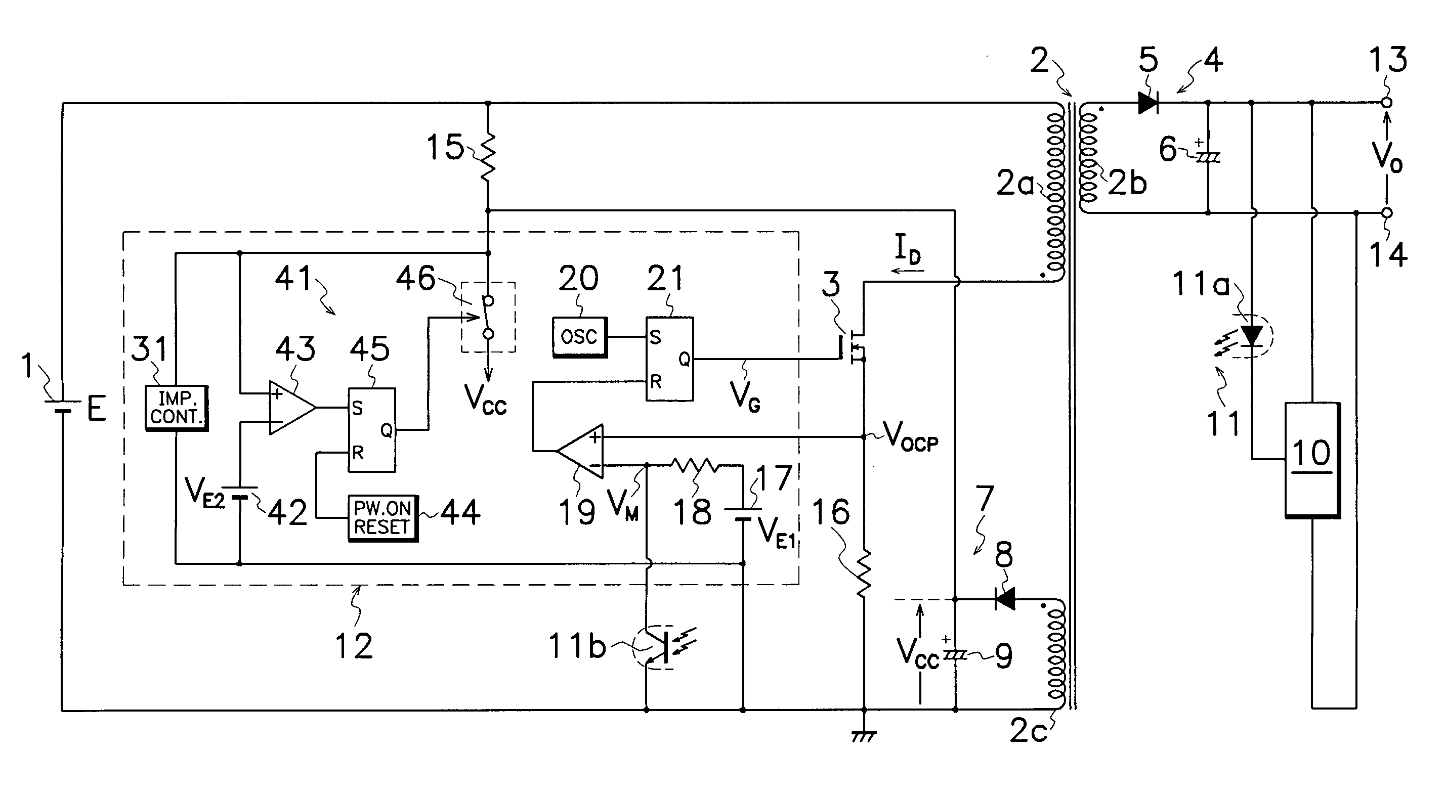
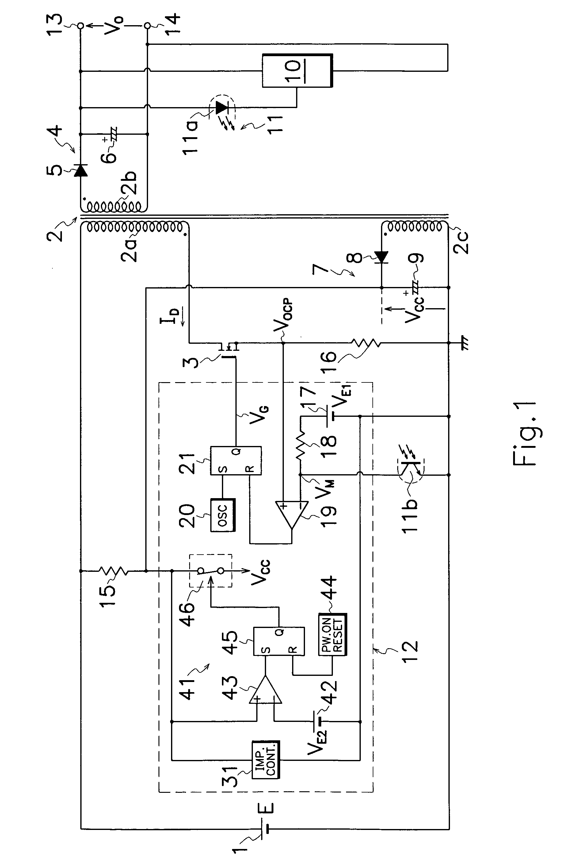
[0021] As shown in FIG. 1, the DC-DC converter of an embodiment according to the present invention, involves a primary control circuit 12 which comprises an impedance controller 31 and a protective circuit 41 for ceasing operation of primary control circuit 12 when power source voltage VCC of primary control circuit 12 exceeds a predetermined voltage level but without Zener diode 22 shown in FIG. 6.

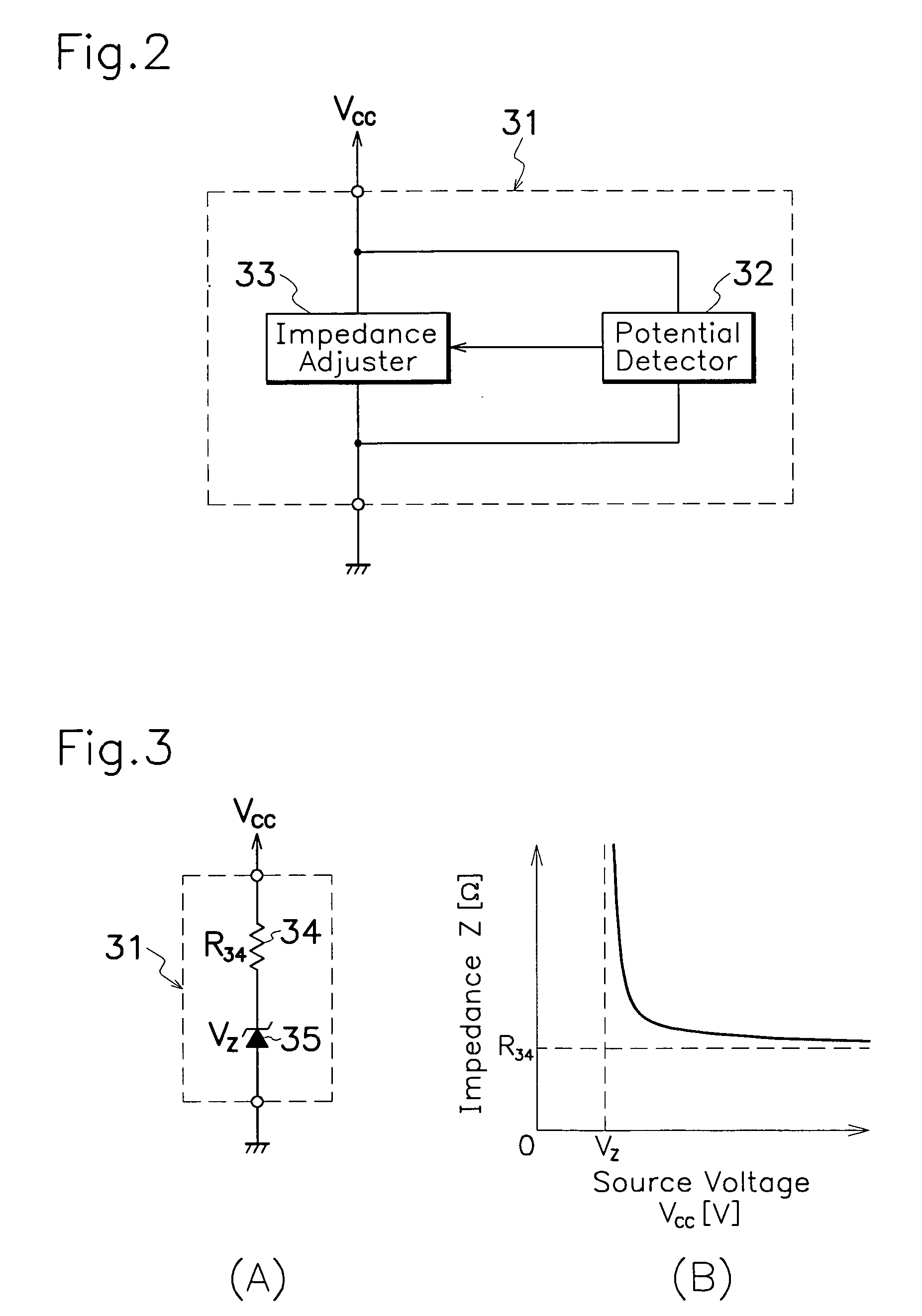
[0022] As illustrated in FIG. 2, impedance controller 31 comprises a potential detector 32 for picking out power source voltage VCC to primary control circuit 12 to produce a detection signal; and an impedance adjuster 33 for regulating power input impedance in primary control cir...


PUM


Abstract

A DC-DC converter for overvoltage protection is provided with a primary control circuit 12 which comprises an impedance controller 31 and a protective circuit 41 for ceasing operation of primary control circuit 12 when power source voltage VCC on primary control circuit 12 exceeds a predetermined voltage level. Impedance controller 31 comprises a potential detector 32 for picking out power source voltage VCC to primary control circuit 12 to produce a detection signal; and an impedance adjuster 33 for adjusting power input impedance Z in primary control circuit 12 in response to the detection signal from potential detector 32 to repress rapid rise in power source voltage on primary control circuit 12.

Description

TECHNICAL FIELD [0001] This invention relates to a DC-DC converter for protecting a built-in control circuit from overvoltage. BACKGROUND OF THE INVENTION [0002] Prior art DC-DC converters, known and widely used as inexpensive DC power sources of the simple structure, utilize a switching element turned on and off to intermittently supply DC voltage from DC power source to a transformer which then converts DC voltage into a high frequency power to supply stabilized DC power to an electric load through a rectifying smoother. A prior art DC-DC converter exemplified in FIG. 6 comprises a primary winding 2a of a transformer 2 and a MOS-FET 3 as a switching element connected in series to a DC power source 1; a main rectifying smoother 4 which comprises a main rectifying diode 5 and a main smoothing capacitor 6 connected to a secondary winding 2b of transformer 2; an auxiliary rectifying smoother 7 which comprises an auxiliary rectifying diode 8 and an auxiliary smoothing capacitor 9 conne...

Claims


Application Information

Patent Timeline
IPC IPC(8): H02H7/122
CPCH02M1/32H02M3/33523
Inventor USUI, HIROSHI
Owner SANKEN ELECTRIC CO LTD
Why Eureka
Try Eureka