Density-matching alkyl push flow for vertical flow rotating disk reactors

a technology of density-matching alkyl push flow and rotating disk reactor, which is applied in the direction of chemically reactive gases, coatings, crystal growth processes, etc., can solve the problems of uneven layer thickness, turbulence between injector flows, and dispersion of reactants, so as to avoid turbulence, improve deposition uniformity, and minimize turbulence

Inactive Publication Date: 2007-06-14
VEECO INSTR
View PDF41 Cites 25 Cited by
  • Summary
  • Abstract
  • Description
  • Claims
  • Application Information

AI Technical Summary

Benefits of technology

[0007] It has been discovered that increased uniformity in the total gas density substantially increases the uniformity of deposition and reduces turbulence and vortices in fluid gas flow within the CVD reaction chamber.
[0008] One aspect of the invention provides a chemical vapor deposition reactor with total gas flow rate / velocity and total gas density substantially matched in the chemical vapor deposition reaction chamber, hence improving uniformity and further reducing non-laminar gas recirculation vortices and turbulence. In one aspect, the system includes a chamber and a substrate carrier mounted for movement within the chamber, most preferably for rotational movement about an axis. The substrate carrier is adapted to hold one or more substrates, most preferably so that surfaces of the substrates to be treated lie substantially perpendicular to the axis. The reactor according to this aspect of the invention desirably includes a gas stream generator arranged to deliver one or more gas streams within the chamber directed toward the substrate carrier at a substantially uniform flow rate. The reactor is advantageously designed such that the chamber holding the substrate carrier therein is maintained at a known, substantially predetermined temperature and pressure.
[0012] A further aspect of the invention includes methods of treating substrates, including rotating a substrate support in a chamber about an axis while supporting one or more substrates to be treated on the support so that surfaces of the substrates lie substantially perpendicular to said axis. The method further includes introducing a reactant gas and a plurality of carrier gas into the chamber so that said gases flow within said chamber toward the surfaces in one or more streams having substantially uniform flow rate at different radial distances from said axis. The method further includes adjusting the relative concentration of each of the plurality of carrier gases with a known molecular weight at each gas flow location such that (given the reactant gas of a known molecular weight and a known concentration at each gas flow location) the total gas density (in terms of total gas molecular weight per unit volume) is substantially equal at each gas flow location. This is preferably performed at a known temperature and pressure in the chamber, so that the gases flow within the chamber towards the surfaces in one or more streams having substantially uniform reactant gas density at different radial distances from said axis thus minimizing turbulence.
[0013] The one or more gas streams are arranged so that different portions of the substrate surfaces at different radial distances from the axis receive substantially the same amount of said reactant gas per unit time per unit area. Most preferably, the step of introducing the carrier gas and reactant gas includes mixing at least some of the reactant gas with the carrier gas so that gas flowing toward radially outward portions of the substrate surfaces has a higher concentration of the reactant gas than gas flowing toward radially inward portions of the surfaces, close to the axis and regulating mass flow of each carrier gas so as to equalize the reactant gas density of each of the resulting gas streams.
[0014] Preferred reactors and methods according to the foregoing aspects of the invention can provide uniform distribution of the reactant gas over the treatment surface of a substrate carrier, such as over the surface of a rotating disk substrate carrier, while avoiding turbulence caused by differing reactant gas velocities. In alkyl / hydride deposition systems, for example, the combination of density and flow rate matching provide for better deposition uniformity due to better diffusion of alkyls, resulting in less inconsistent growth rate responses from the individual alkyl injectors. Moreover, boundary layer thickness is more uniform from zone to zone since it is not disturbed with the local changes in densities, given that boundary layer thickness is directly proportional to the density. Additionally, increased boundary layer uniformity also triggers reduced buoyancy-induced recirculation, thus allowing a wider array of processing options in process parameters space.

Problems solved by technology

While this variation in gas flow rate / velocity helps to ensure a more uniform layer thickness, it may also cause turbulence between the injector flows due to their varying velocities.
Also, the risk of side effects such as uneven layer thickness, dissipation of reactant, or premature condensation of reactant may be increased.

Method used


Image

  • Density-matching alkyl push flow for vertical flow rotating disk reactors
  • Density-matching alkyl push flow for vertical flow rotating disk reactors
  • Density-matching alkyl push flow for vertical flow rotating disk reactors

Examples


Embodiment Construction

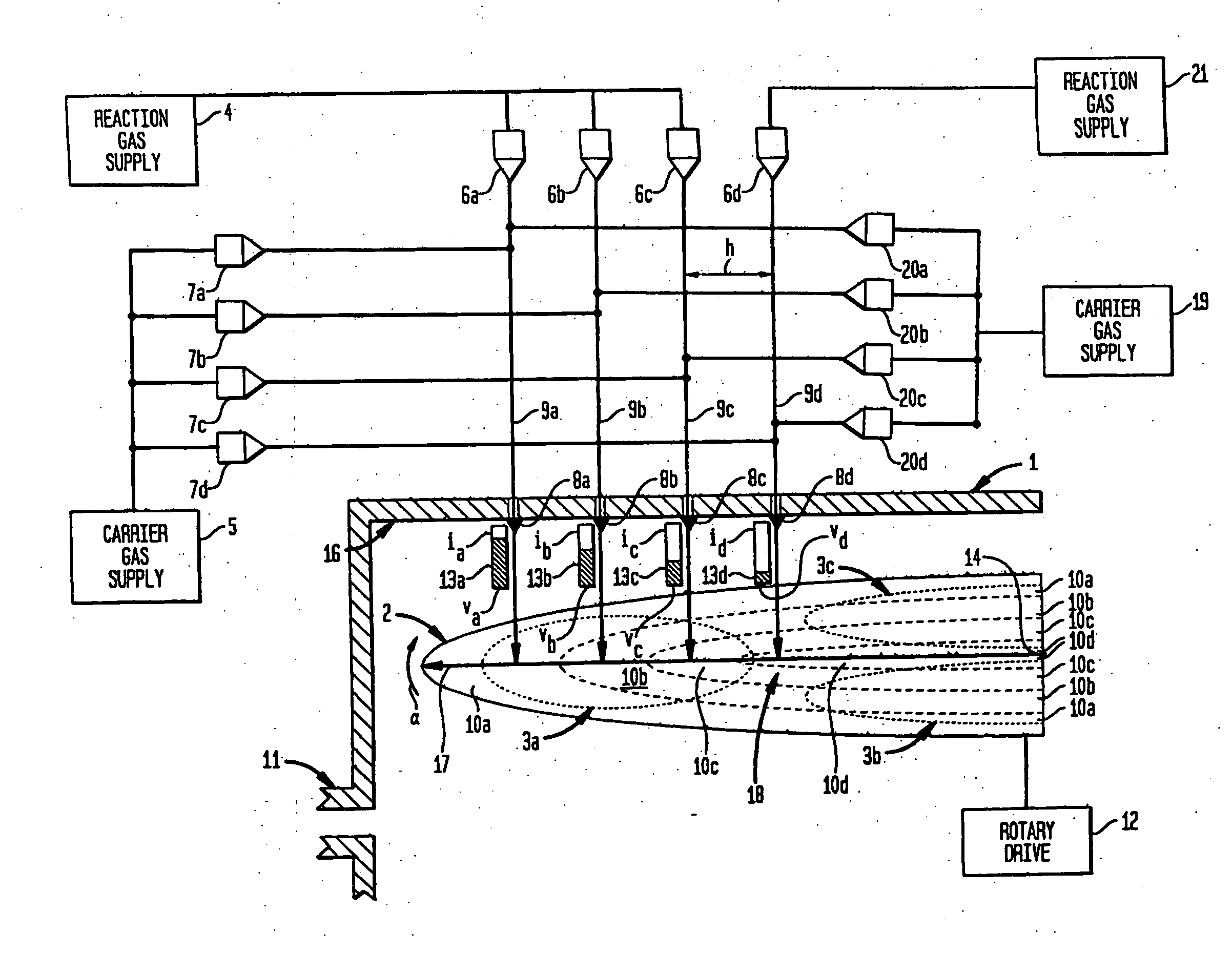
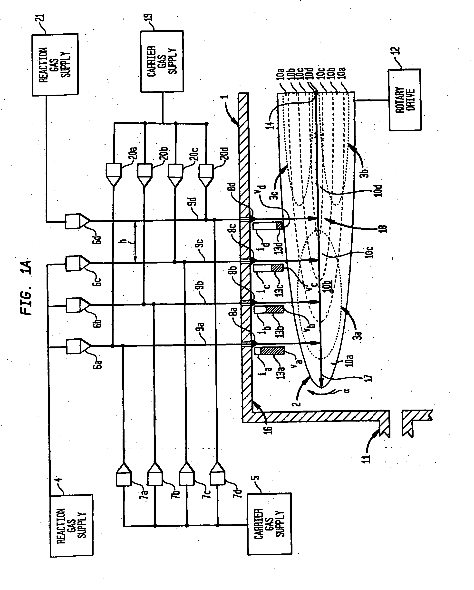
[0025] An apparatus according to one embodiment of the invention, depicted schematically in FIG. 1, includes a reaction chamber 1 and a substrate carrier 2. The chamber includes a top wall 16 and an exhaust port 11. The substrate carrier 2 is mounted within the chamber 1 for rotation about a central axis 14 and connected to a rotary drive system 12 so that the substrate carrier 2 can be rotated around the axis 14. The substrate carrier 2 defines a treatment surface 18 in the form of a generally planar disc perpendicular to axis 14 and facing toward top wall 16. Only a portion of such surface 18 is depicted in FIG. 1. The reaction chamber 1 is equipped with other conventional elements (not shown) for facilitating the desired epitaxial growth reaction as, for example, a heating system for maintaining the substrate carrier at an elevated temperature, temperature monitoring devices and pressure monitoring devices, such as, for example, a sucspetor for heating the substrate carrier. Thes...


PUM

PropertyMeasurementUnit
pressuresaaaaaaaaaa
molecular weightsaaaaaaaaaa
densityaaaaaaaaaa

Abstract

In a rotating disk reactor for growing epitaxial layers on substrate or other CVD reactor system, gas directed toward the substrates at gas inlets at different radial distances from the axis of rotation of the disk has both substantially the same gas flow rate / velocity and substantially the same gas density at each inlet. The gas directed toward portions of the disk remote from the axis may include a higher concentration of a reactant gas than the gas directed toward portions of the disk close to the axis, so that portions of the substrate surfaces at different distances from the axis receive substantially the same amount of reactant gas per unit area, and a combination of carrier gases with different relative molecular weights at different radial distances from the axis of rotation are employed to substantially make equal the gas density in each region of the reactor. The system may be applied with a combination or carrier gases at multiple gas inlets, a combination of carrier and reactant gases at multiple inlets, and may be used with an arbitrarily large number of gases, when at least two gases of different molecular weights are provided. A linear flow pattern is achieved within the reactor, avoiding laminar recirculation areas, and permitting uniform deposition and growth of epitaxial layers on the substrate.

Description

CROSS-REFERENCE TO RELATED APPLICATIONS [0001] This application is a continuation-in-part of U.S. application Ser. No. 10 / 568,794, filed on Feb. 17, 2006, the disclosure of which is incorporated herein by reference, which is a national phase entry under 35 U.S.C. § 371 of International Application No. PCT / US2003 / 026112 filed Aug. 20, 2003, published in the United States and internationally, which is incorporated herein by reference.TECHNICAL FIELD OF THE INVENTION [0002] The present invention relates to metal organic chemical vapor phase deposition reactors. More particularly, the present invention relates to rotating disk reactors in which one or more gases are injected onto the surface of a rotating substrate to grow epitaxial layers thereon. BACKGROUND OF THE INVENTION [0003] Vertical high-speed rotating disk reactors, in which the gas or gases are injected downwardly onto a substrate surface rotating within a reactor, are frequently employed for metal organic chemical vapor depo...

Claims


Application Information

Patent Timeline
Patent Type & Authority Applications(United States)
IPC IPC(8): C23C16/00C23C16/44C23C16/455C23C16/458C30B25/14
CPCC23C16/45563C30B25/165C23C16/45578C23C16/45574C23C16/4584C30B25/14C23C16/44H01L21/0262C30B25/08C30B25/12C23C16/455C23C16/45565C23C16/458C23C16/52
Inventor MITROVIC, BOJANGURARY, ALEXQUINN, WILLIAMARMOUR, ERIC A.
Owner VEECO INSTR
Why Eureka
Try Eureka