System and method for controlling vehicular traffic flow

a technology of vehicular traffic and system and method, applied in the field of wireless networking, can solve the problems of traffic flow problem, traffic throughput decline, significant traffic flow problem, etc., and achieve the effect of increasing traffic throughput and safety, and reducing the distribution of vehicles

Inactive Publication Date: 2007-06-14
HONEYWELL INT INC
View PDF28 Cites 68 Cited by
  • Summary
  • Abstract
  • Description
  • Claims
  • Application Information

AI Technical Summary

Benefits of technology

[0007] The present invention provides a system and method for controlling vehicular traffic flow, by creating a communication system between vehicles that allows the vehicles to share their respective velocities and acceleration or deceleration rates. Thus, each vehicle within the system can respond immediately to any acceleration or deceleration rate changes of the surrounding vehicles (e.g., the vehicle directly in front, directly in back, and in the adjacent lane). Essentially, the present invention provides a wireless vehicular train, with a queue of cars linked together by a stiff, wireless communications “chain”. Notably, the term “vehicle” is not limited only to land-based vehicles (e.g., motor vehicles), and the present invention can include within its scope airborne vehicles (e.g., multiple aircraft flying in close formation, military aircraft flying in drone formation, etc.). In accordance with a preferred embodiment of the present inventio...

Problems solved by technology

As such, the “slinky” effect is a significant traffic flow problem that often leads to rear-end collisions and other types of collisions, and traffic throughput is also decreased as a result.
Another significant traffic flow problem occurs if a vehicle immediately in front of another vehicle suddenly slows down or stops.
Also, if one or more vehicles swerve to avoid a collision, the swerving vehicles can cause a collision in the adjacent lane(s).
Yet another significant traffic flow problem occurs when a number of vehicles stopped in a queue (e.g., at a red light) begin accelerating (e.g., the light has changed to green).
Thus, after the first of the vehicles in the queue begins to accelerate, there is a substantial lapse of time before the vehicles farther down in the queue can begin t...

Method used


Image

  • System and method for controlling vehicular traffic flow
  • System and method for controlling vehicular traffic flow
  • System and method for controlling vehicular traffic flow

Examples


Embodiment Construction

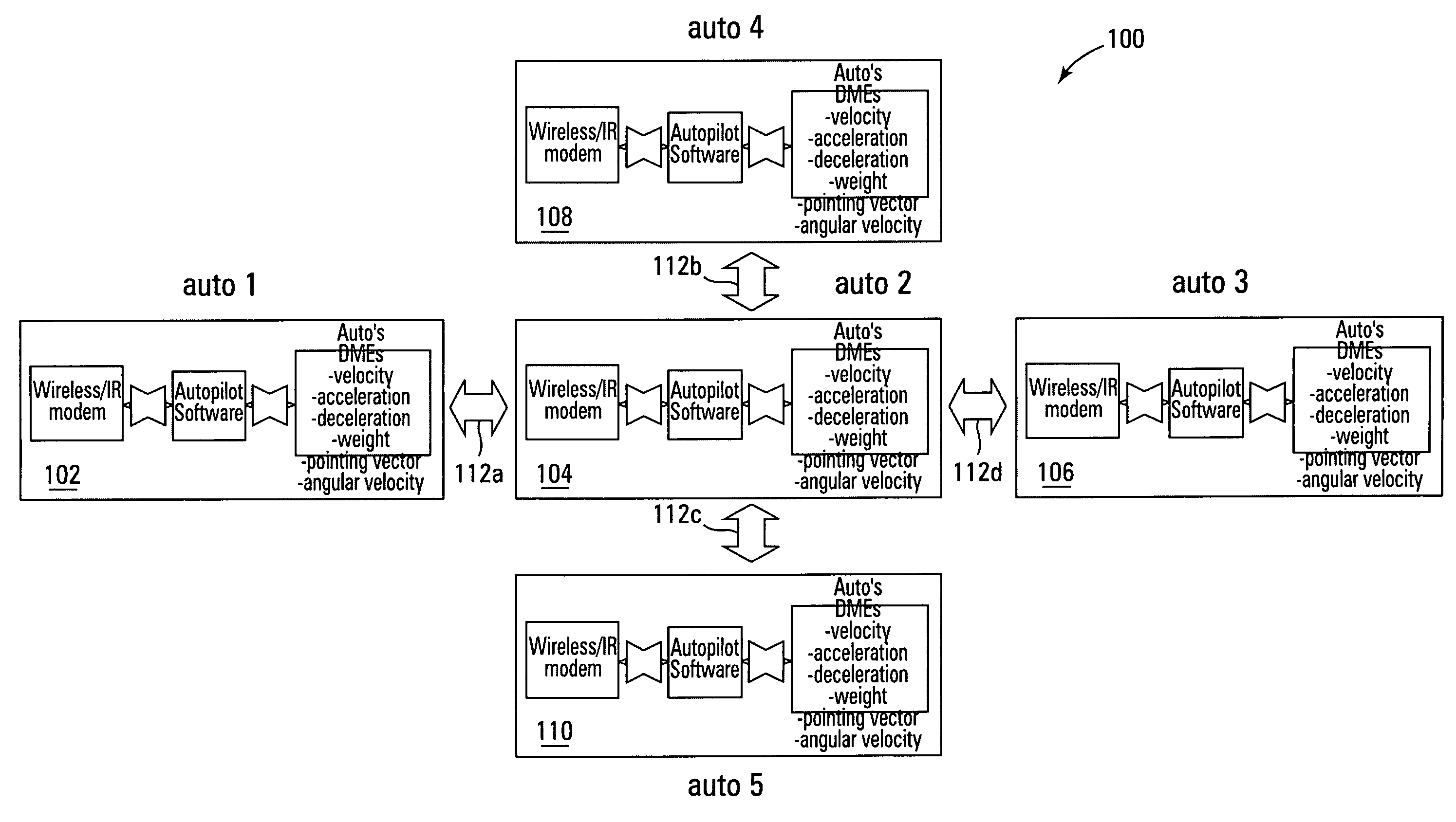
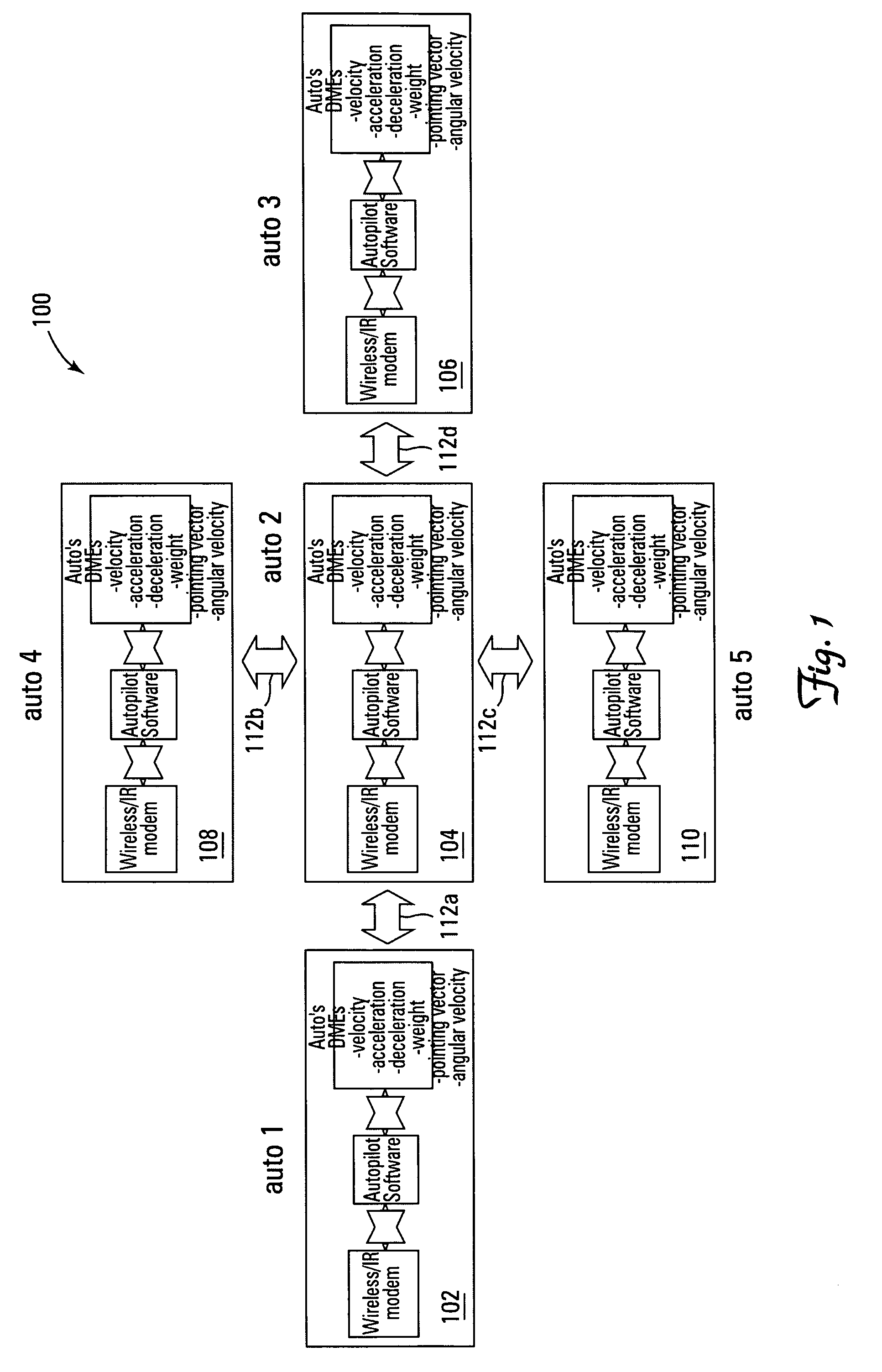
[0013] With reference now to the figures, FIG. 1 depicts a block diagram of an example system 100 for controlling vehicular traffic flow, which can be used to implement a preferred embodiment of the present invention. For this example embodiment, system 100 includes a plurality of automotive vehicles 102, 104, 106, 108, 110. Each vehicle 102-110 can communicate with at least one other vehicle 102-110 via a respective wireless communication link 112a-112d. For clarity and ease of understanding, it may be assumed that vehicles 102-110 are automobiles, but the present invention is not intended to be so limited and can include within its scope other types of vehicles that are typically arranged as queued vehicular traffic (e.g., trucks, buses, vans, motorcycles, etc.). Notably, the present invention also includes within its scope airborne vehicles (e.g., multiple aircraft flying in close formation, military aircraft flying in drone formation, etc.). Also, for this example, it may be ass...


PUM


Abstract

A system and method for controlling vehicular traffic flow is disclosed, which creates a communication system between vehicles that allows the vehicles to share their respective velocities and acceleration or deceleration rates. Thus, each vehicle within the system can respond immediately to any acceleration or deceleration rate changes of the surrounding vehicles (e.g., the vehicle directly in front, directly in back, and in the adjacent lane). Essentially, the system functions similar to a wireless vehicular train, with a queue of cars linked together by a stiff, wireless communications “chain”. Notably, the term “vehicle” is not limited only to land-based vehicles (e.g., motor vehicles), and the system can include airborne vehicles (e.g., multiple aircraft flying in close formation, military aircraft flying in drone formation, etc.). For example, a system for controlling vehicular traffic flow is disclosed, which includes in each vehicle of a plurality of vehicles, a wireless or infrared (IR) modem for inter-vehicular communications, a range finder for determining the distance and closing rate between vehicles, a processing unit for retrieving vehicular operational data (e.g., velocity, angular velocity, acceleration rate, deceleration rate, braking pressure, weight, pointing vector, etc.) and executing flow control system software instructions, and a vehicular flow control communications protocol that enables the communication of various flow control parameters between vehicles via the wireless or IR modem. Thus, each vehicle in the system “knows” what the surrounding vehicles are doing and can respond immediately to changes in the traffic flow. As such, the system minimizes the distribution of vehicles' velocities in the queue, and increases traffic throughput and safety as a result.

Description

FIELD OF THE INVENTION [0001] The present invention relates generally to the wireless networking field, and more specifically, but not exclusively, to a system and method for controlling vehicular traffic flow. BACKGROUND OF THE INVENTION [0002] A slow down (or speed up) of queued motor vehicle traffic often creates what is known as the “slinky” effect. For example, if a blockage (accident, obstacle, etc.) impedes traffic flow in a lane, the vehicles in that lane have to merge with the flow of an adjacent lane. Consequently, long after the blockage is cleared, the perturbed lanes retain a “slinky” effect due to a “phantom” blockage caused by a large distribution of vehicles' velocities where the blockage actually occurred. In other words, a velocity wave is created when the vehicles in a queue are traveling at different speeds (e.g., some of the vehicles in the queue are stopped, accelerating, decelerating, or cruising at a constant speed). As such, the “slinky” effect is a signific...

Claims


Application Information

Patent Timeline
IPC IPC(8): G08G1/00
CPCB60W40/04G08G1/163
Inventor HENGST, TIMOTHY M.
Owner HONEYWELL INT INC
Why Eureka
Try Eureka