Geometric configuration and confinement for deflagration to detonation transition enhancement

a technology of geometries and confinements, applied in the direction of machines/engines, intermittent jet plants, lighting and heating apparatus, etc., can solve the problems of relative long run-up length and problem of fuel-air mixture detonation, and achieve the effect of accelerating the stretching of flames, reducing run-up length to detonation, and enhancing mixing

Inactive Publication Date: 2007-06-21
GENERAL ELECTRIC CO
View PDF7 Cites 29 Cited by
  • Summary
  • Abstract
  • Description
  • Claims
  • Application Information

AI Technical Summary

Benefits of technology

[0007] In an embodiment of the present invention, a turbulence generator is positioned upstream of the spark region to aid in the mixing of the fuel-air mixture and a shaped center body is positioned within the tube to further enhance mixing and accelerate the stretching of the flame, so as to reduce the run-up length to detonation. Specifically, the present invention employs at least one fuel-air mixer located upstream of the ignition source which imparts turbulence into the mixture, which enhances mixing. Further, at least one shaped center body is placed within the flow path of the fuel-air mixture to further enhance the mixing. The shaped center body is configured such that it imparts additional turbulence into the flow.
[0008] In an embodiment of the present invention, the shaped center-body contains a number of recessions, dimples or protrusions which further interact with the flow, thus imparting additional turbulence in the flow, thus reducing the overall run-up length.
[0009] By adjusting various parameters, such as the shape, size, and surface contour of the center body, the positioning and shape of the fuel-air mixer, and the positioning of the spark or ignition source, the present invention reduces the DDT run-up length and run-up time in a pulse detonation combustor, allowing for the construction of more compact and practical PDC.

Problems solved by technology

However, a problem with existing smooth walled tube structures is the relative long run-up length necessary to achieve detonation of the fuel-air mixture.
This run-up length is problematic when trying to incorporate the pulse detonation combustor in applications where space and weight are important factors, such as aircraft engines.

Method used


Image

  • Geometric configuration and confinement for deflagration to detonation transition enhancement
  • Geometric configuration and confinement for deflagration to detonation transition enhancement
  • Geometric configuration and confinement for deflagration to detonation transition enhancement

Examples


Embodiment Construction

[0019] The present invention will be explained in further detail by making reference to the accompanying drawings, which do not limit the scope of the invention in any way.

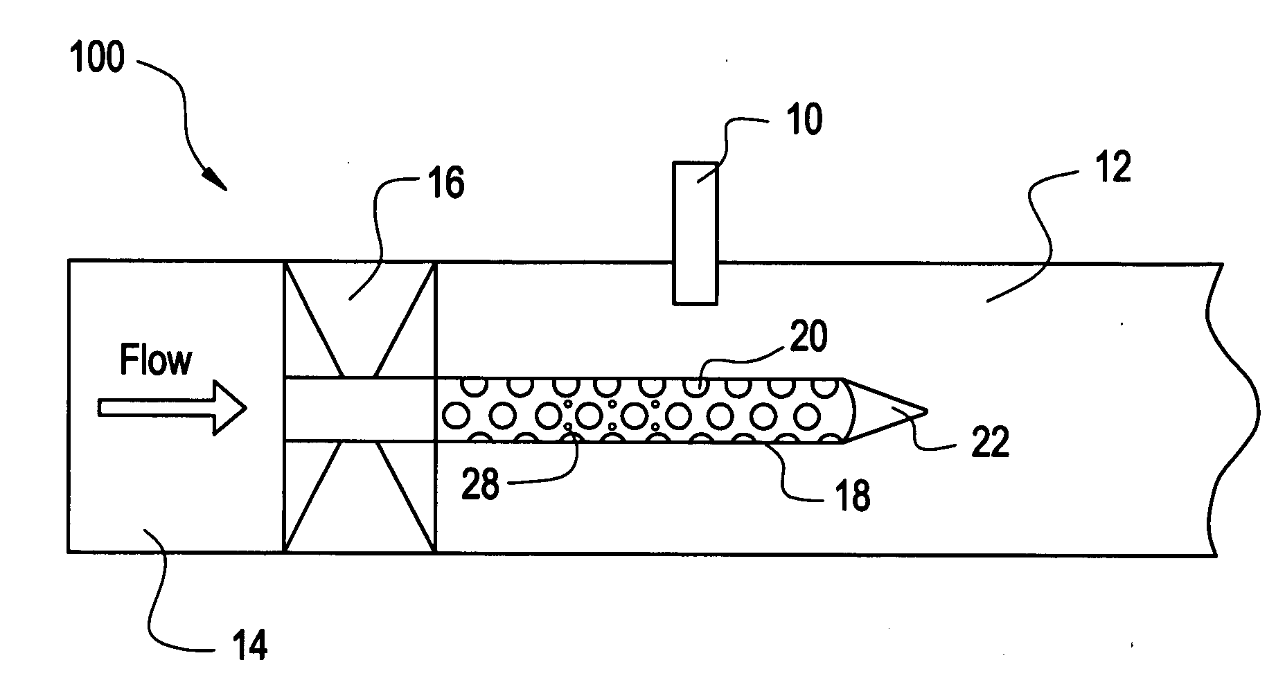
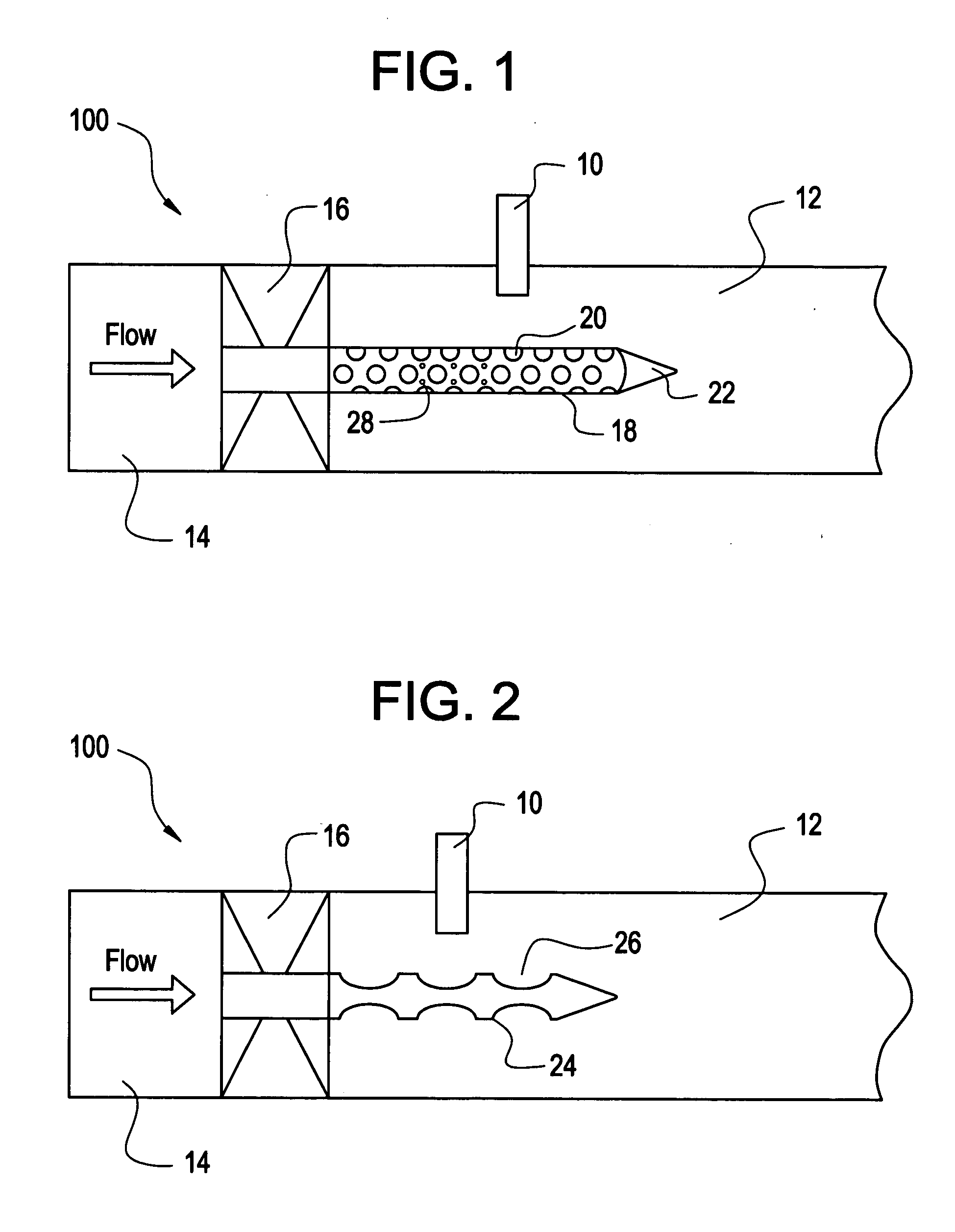
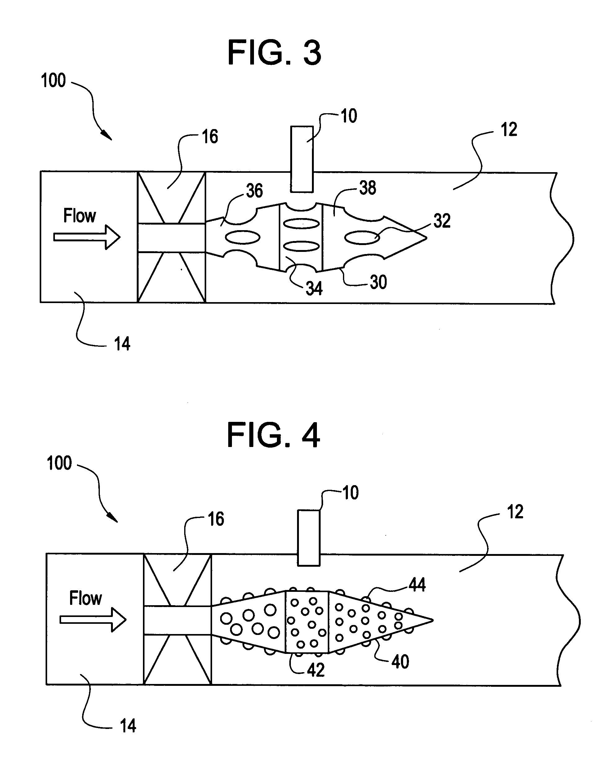
[0020]FIGS. 1 through 6 depict a cross-sectional side view of a pulse detonation combustor 100 according to various embodiments of the present invention. The pulse detonation combustors 100 contain a forward flow section 14 positioned upstream of a fuel-air mixer 16, which is, in turn, positioned upstream of an ignition source 10, a detonation chamber 12, and a center body 18 (FIG. 1). Each of the FIGS. 1 through 6 depict an alternative embodiment of the present invention, in which the center body is show with various alternative configurations.

[0021] Turning now to FIG. 1, an exemplary embodiment of the present invention is shown. In this embodiment, the pulse detonation combustor 100 contains a forward flow section 14 positioned upstream of a fuel-air mixer 16, which is, in turn, positioned upstream of an igni...


PUM


Abstract

A pulse detonation combustor is provided with a fuel-air mixer located upstream from a detonation chamber. A fuel-air mixture exits the fuel-air mixer and enters the detonation chamber, where it is ignited by an ignition source. The flow from the fuel-air mixer passes over the surface of a center body, which extends downstream from the fuel-air mixer. The surface of the center body contains at least one turbulence generator, which imparts additional turbulence in the fuel-air mixture passing through the chamber. The turbulence generator aids in the mixing of the fuel and air of the fuel-air mixture to enhance the deflagration to detonation transition within the pulse detonation combustor.

Description

BACKGROUND OF THE INVENTION [0001] This invention relates to an apparatus and method for enhancing mixing of a fuel-air mixture in a pulse detonation combustor to reduce the overall run-up time and / or distance to detonation of the mixture. [0002] In pulse detonation combustors, a mixture of fuel and air is ignited and is transitioned from deflagration to detonation, so as to produce supersonic shock waves, which can be used to provide thrust, among other functions. This deflagration to detonation transition (DDT) typically occurs in a smooth walled tube or pipe structure, having an open end through which the exhaust exits. [0003] The deflagration to detonation process begins when a fuel-air mixture in a tube is ignited via a spark or other source. The subsonic flame generated from the spark accelerates as it travels along the length of the tube due to various chemical and flow mechanics. As the flame reaches sonic velocity, shocks are formed which reflect and focus creating “hot spo...

Claims


Application Information

Patent Timeline
Patent Type & Authority Applications(United States)
IPC IPC(8): F02C5/00
CPCF02C5/00F02K7/02Y02T50/675F23R3/16F23R7/00F23R3/14Y02T50/60
Inventor RASHEED, ADAMDEAN, ANTHONY JOHNTANGIRALA, VENKAT ESWARLUCHAPIN, DAVID MICHAEL
Owner GENERAL ELECTRIC CO
Why Eureka
Try Eureka