Technique for providing an inductively coupled radio frequency plasma flood gun

a radio frequency flood gun and inductive coupling technology, applied in the field of ion implantation, can solve the problems of metal contamination, permanent damage, and the number of problems of existing pfgs,

Inactive Publication Date: 2007-06-21
VARIAN SEMICON EQUIP ASSOC INC
View PDF13 Cites 31 Cited by
  • Summary
  • Abstract
  • Description
  • Claims
  • Application Information

AI Technical Summary

Benefits of technology

[0008]A technique for providing an inductively coupled radio frequency plasma flood gun is disclosed. In one particular exemplary embodiment, the technique may be realized as a plasma flood gun in an ion implantation system. The plasma flood gun may comprise a plasma chamber having one or more apertures. The plasma flood gun may also comprise a gas source capable of supplying at least one gaseous substance to the plasma chamber. The plasma flood gun may further comprise a pow

Problems solved by technology

The resulting positive potentials can create strong electric fields in some miniature structures and may cause permanent damage.
Existing PFG's suffer from a number of problems.
A significant problem is metal contamination.
The tungsten filament is gradually consumed and tungsten atoms may contaminate the ion implantation system as well as wafers processed therein.
Metal electrodes or other metal components placed inside the plasma chamber may cause similar contaminations.
The plasma tends to corrode the metal electrodes or similar metal surfaces and lead to metal contamination.
Although the contamination problem might be alle

Method used


Image

  • Technique for providing an inductively coupled radio frequency plasma flood gun
  • Technique for providing an inductively coupled radio frequency plasma flood gun
  • Technique for providing an inductively coupled radio frequency plasma flood gun

Examples


Embodiment Construction

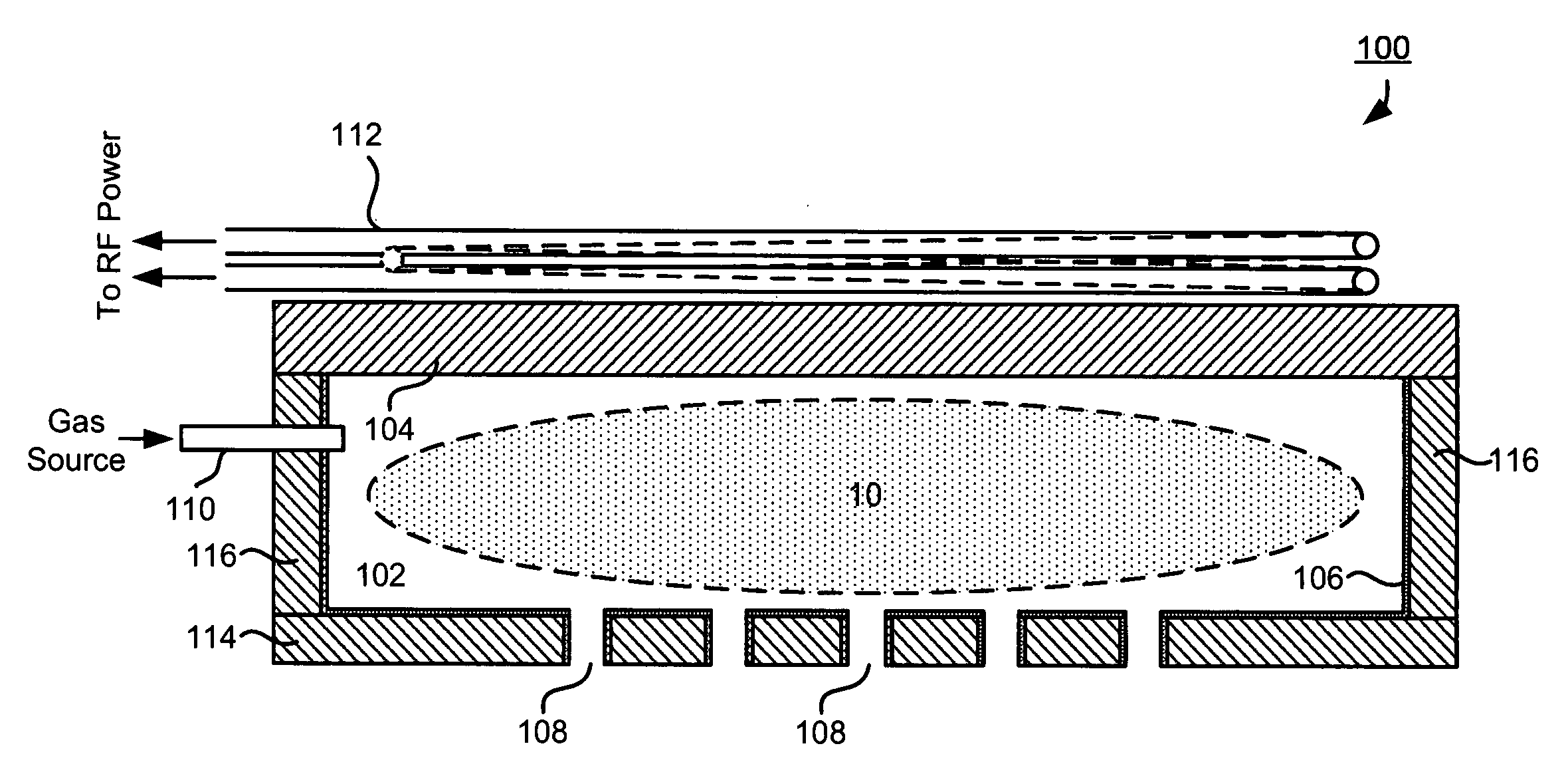
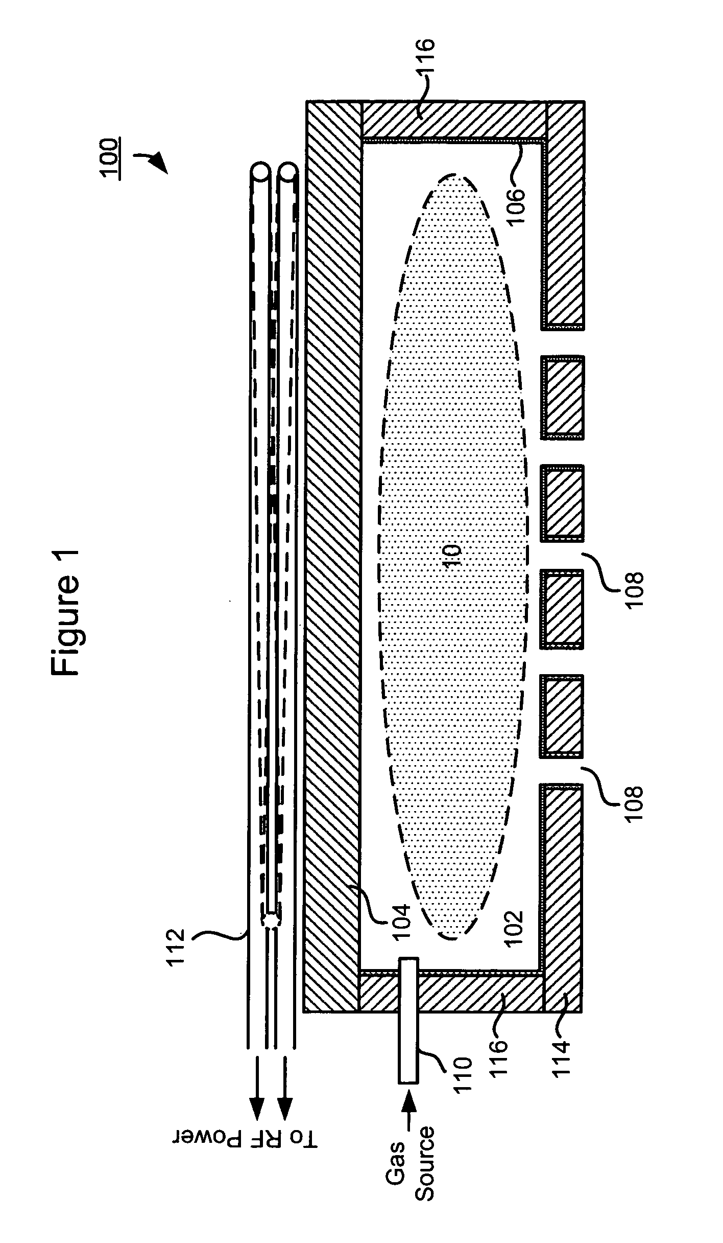
[0032]Referring to FIG. 1, there is shown a side view of an exemplary PFG 100 in accordance with an embodiment of the present disclosure.

[0033]The PFG 100 may comprise a plasma chamber 102 that has a substantially metal-free inner surface. In a preferred embodiment, no metal electrode or metal component may be placed inside the plasma chamber 102. Nor is there any exposed metal or metal compound in the plasma chamber 102. One side of the plasma chamber 102 may be a dielectric interface 104 that separates the inside of the plasma chamber 102 from a coil 112. The dielectric interface 104 may be made of quartz and / or other dielectric materials that contains no metal or metal compound. The other portions (e.g., an aperture plate 114 or sidewall 116) of the plasma chamber 102 may be made out of a non-metallic conductive material such as graphite or silicon carbide (SiC). Alternatively, the other portions of the inner surface may have a coating 106 of a non-metallic conductive material (e...


PUM

PropertyMeasurementUnit
Lengthaaaaaaaaaa
Lengthaaaaaaaaaa
Lengthaaaaaaaaaa

Abstract

A technique for providing an inductively coupled radio frequency plasma flood gun is disclosed. In one particular exemplary embodiment, the technique may be realized as a plasma flood gun in an ion implantation system. The plasma flood gun may comprise: a plasma chamber having one or more apertures; a gas source capable of supplying at least one gaseous substance to the plasma chamber; and a power source capable of inductively coupling radio frequency electrical power into the plasma chamber to excite the at least one gaseous substance to generate a plasma. Entire inner surface of the plasma chamber may be free of metal-containing material and the plasma may not be exposed to any metal-containing component within the plasma chamber. In addition, the one or more apertures may be wide enough for at least one portion of charged particles from the plasma to flow through.

Description

CROSS-REFERENCE TO RELATED APPLICATIONS[0001]This patent application claims priority to U.S. Provisional Patent Application No. 60 / 751,218, filed Dec. 19, 2005, which is hereby incorporated by reference herein in its entirety.FIELD OF THE DISCLOSURE[0002]The present disclosure relates generally to ion implantation and, more particularly, to a technique for providing an inductively coupled radio frequency plasma flood gun.BACKGROUND OF THE DISCLOSURE[0003]During an ion implantation process, a semiconductor wafer is typically bombarded with positively charged ions. Unhindered, these positively charged ions may build up a positive charge on insulated portions of the wafer surface and lead to positive potentials thereon. The energetic ions can also contribute to further wafer charging through secondary electron emission from the wafer. The resulting positive potentials can create strong electric fields in some miniature structures and may cause permanent damage. A plasma flood gun (PFG)...

Claims


Application Information

Patent Timeline
IPC IPC(8): H01J7/24C23C16/00
CPCH01J37/026H01J37/3171H01J2237/0041H01J2237/0044H01J37/317H01J37/32H01J37/36
Inventor KURUNCZI, PETER F.LOW, RUSSELLPEREL, ALEXANDER S.COBB, ERIC R.WRIGHT, ETHAN ADAM
Owner VARIAN SEMICON EQUIP ASSOC INC
Why Eureka
Try Eureka