Radial farm tire for high clearance sprayers

a technology of high-clearance sprayer and pneumatic tire, which is applied in the field of tires, can solve the problems of increasing the load, and affecting the service life of the lugs of such conventional agricultural pneumatic tires

Inactive Publication Date: 2007-06-21
THE GOODYEAR TIRE & RUBBER CO
View PDF6 Cites 5 Cited by
  • Summary
  • Abstract
  • Description
  • Claims
  • Application Information

AI Technical Summary

Benefits of technology

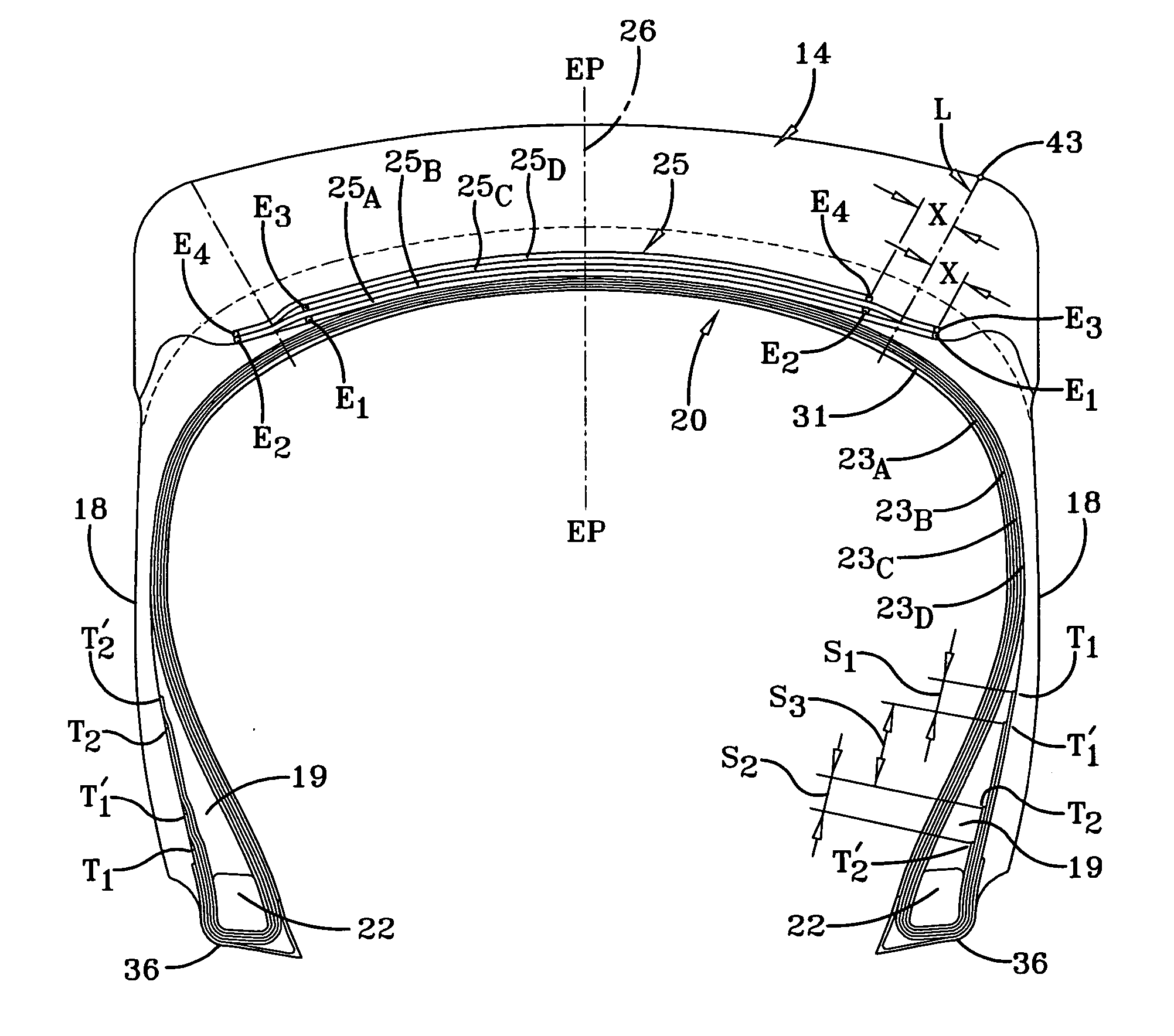
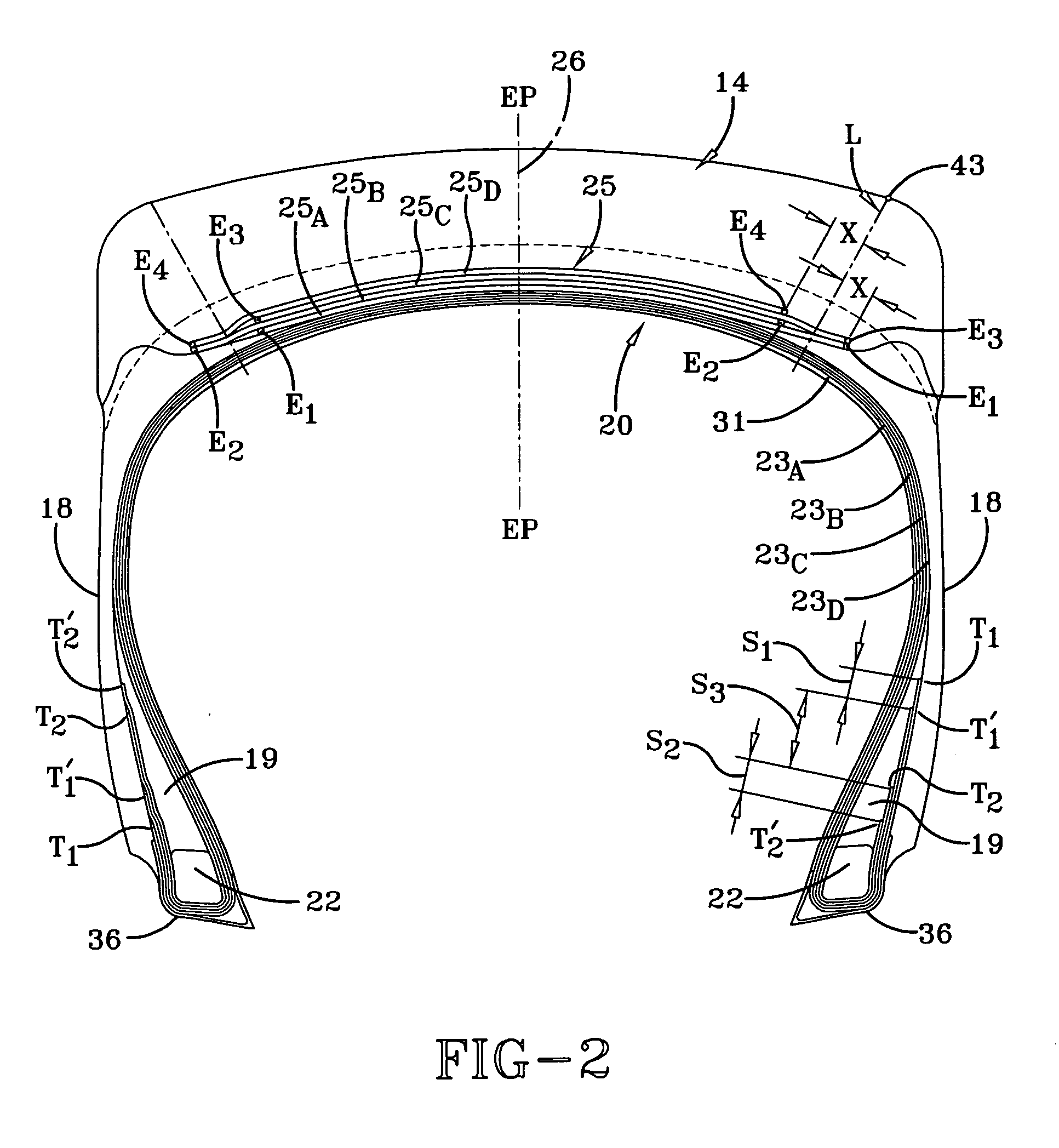
[0044] The advantage of the present invention is believed to be derived from the second set of plies 23C, 23D having a pair of low ply endings T2, T2′, but being adjacent the bead cores 21 and 22 that absorb much of the forces of the weight and torque of the tire under load so that the high ply endings which normally would initiate any separation under such extreme loads only are exposed to far less of the stress leading to less probability of a turnup separation from occurring. Accordingly while all four plies are carrying the load between the bead cores 21, 22 the radially inner plies 23C and 23D and their low turnups are securely anchoring the carcass 20 and reducing the stress on the high turnup ends of plies 23A and 23B.

Problems solved by technology

Because row-crop field sprayers are extremely massive agricultural-machines, their pneumatic tires must have the ability to carry large loads.
Because the tire load increases as the footprint narrows, conventional agricultural pneumatic tires cannot satisfy the full range of performance and design parameters required for row-crop field sprayer service.
In particular, the lugs of such conventional agricultural pneumatic tires experience adverse consequences, such as cracking, tearing or, at the least, irregular wear patterns, resulting from hard surface roading.
The inferior performance of conventional agricultural pneumatic tires arises from the faceted leading edge of the lugs, which define outside corners that provide stress concentration points under the conditions of high loading and fast speed.
In particular, tires having conventional lug widths are prone to deflection which creates cracking, tearing and irregular wear patterns.
These turnup separations eventually can cause the sidewalls to crack and cause a loss of inflation.
Therefore, conventional agricultural pneumatic tires for service with row-crop field sprayers are particularly susceptible to the aforementioned adverse consequences, which significantly reduce tire durability.

Method used


Image

  • Radial farm tire for high clearance sprayers
  • Radial farm tire for high clearance sprayers
  • Radial farm tire for high clearance sprayers

Examples


Embodiment Construction

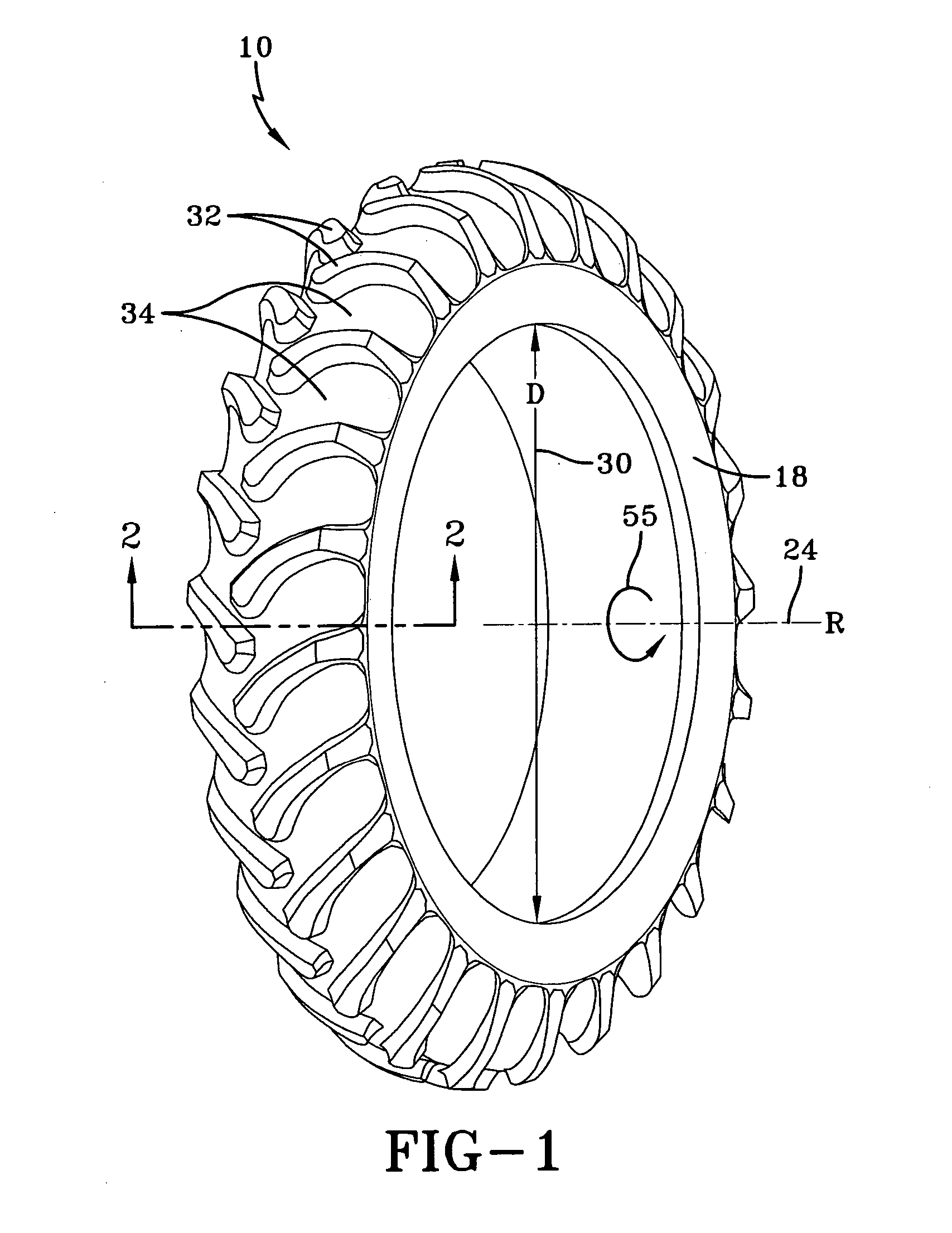
[0037] Although the invention will be described next in connection with certain embodiments, the invention is not limited to practice in any one specific type of row-crop field sprayer. It is contemplated that the pneumatic tires of the invention can be used with a variety of agricultural machinery having a high center of gravity and a large mass, including but not limited to row-crop field sprayers. Exemplary row-crop field sprayers with which the pneumatic tires of the invention can be used are commercially available, for example, from the Model 4710 and Model 6700 Self-Propelled Sprayers manufactured by John Deere (Moline, Ill.) and the New Holland Model SF550 self-propelled sprayer manufactured by CNH Global N.V. (Lake Forest, Ill.), and such commercially available row-crop field sprayers can be equipped with pneumatic tires constructed in accordance with the present invention. The description of the invention is intended to cover all alternatives, modifications, and equivalent ...


PUM


Abstract

The invention is directed to a high aspect ratio agricultural pneumatic tire having a tread, a belt reinforcing structure and a carcass. The tread includes a circumferential inner tread and a plurality of lugs each projecting radially outward from the inner tread. The belt reinforcing structure includes four or more belt layers reinforced by synthetic cords and underlying the tread. The carcass has a pair of bead portions each having a core and a bead filler above each bead core and two pair of first and second carcass plies. Each ply is reinforced by synthetic cords oriented radially and wrapped from the inside of each bead core around to an axially outer turnup end. The first pair of plies is radially inward and adjacent the second pair of plies between the bead cores and having the turnup ends wrapped about the bead cores and the turnup end of the second pair of plies. The turnup end of the first pair of plies extends outwardly and radially along said bead filler to a terminal end T1, T1′ and said turnup ends of said second pair of plies extends to turnup ends T2, T2′ wherein T1, T1′ are located between 60% and 80% of a location Y defined as the radial location of maximum section width (SW) of the tire and the second pair of plies have the terminal ends T2, T2′ extend above the bead cores to a location 30% to 50% of Y. The aspect ratio is preferably greater than 85%, more preferably about 90% or greater. The ply cords are nylon and the belt cords are aramid to form a substantially synthetic textile carcass.

Description

FIELD OF THE INVENTION [0001] The present invention generally relates to tires and, more specifically, to pneumatic tires for row-crop field sprayers and like agricultural machinery. BACKGROUND OF THE INVENTION [0002] Self-propelled row-crop field sprayers are specialized agricultural machinery for applying liquids, such as fertilizers or insecticides, to crops planted and grown in multiple parallel rows. Adjacent pairs of rows are tightly spaced for maximizing the plant density of the row crop being grown. As a result, row-crop field sprayer tires have a narrow section width and a high aspect ratio so that the tire can travel within the intra-row space. Because row-crop field sprayers are extremely massive agricultural-machines, their pneumatic tires must have the ability to carry large loads. Pneumatic tires for the row-crop field sprayer also have to have a large rim diameter so that the field sprayer can clear the plants in the crop rows. Moreover, the pneumatic tires must exhib...

Claims


Application Information

Patent Timeline
Patent Type & Authority Applications(United States)
IPC IPC(8): B60C9/00
CPCB60C9/08B60C9/20Y10T152/10504B60C15/06B60C11/0311B60C2015/009
Inventor RIELLY, KEVIN MICHAELMCGAFFICK, THOMAS EDWARD
Owner THE GOODYEAR TIRE & RUBBER CO
Why Eureka
Try Eureka