
Heating and cooling system for biological materials

a biological material and cooling system technology, applied in the field of biological materials, can solve the problems of less uniformity of active materials, increased difficulty in reducing temperature, and degradation of active materials, so as to reduce the thickness of ice formed, reduce the compartmentalization of medium, and minimize the effect of ice formation

Inactive Publication Date: 2007-06-21
GENENTECH INC
View PDF68 Cites 3 Cited by
  • Summary
  • Abstract
  • Description
  • Claims
  • Application Information

AI Technical Summary

Benefits of technology

The present invention is a system for heating and cooling biological materials. It includes a vessel with a vertical inner wall and a plurality of vertical conduit portions containing heat transfer fluid. The conduit portions are positioned at different distances from the inner wall, which allows for efficient heat transfer without forming too much ice on the cooling surfaces. The system also minimizes the risk of damage to the biological material during removal and insertion of the heat transfer surfaces. The technical effects of the invention include reducing the thickness of ice and minimizing the risk of damage to the biological material.

Problems solved by technology

If the freezing or thawing is too slow, the active material may be subject to degradation from concentration gradients.
These problems can be exacerbated by compartmentalization of the material that is freezing or thawing.
Overall, uneven freezing and thawing can lead to less uniformity in the active material and challenges in properly mixing it during the freeze and thaw processes.
An additional problem is that the materials best suited for contact with biological materials have relatively poor heat transfer properties.
The attachment of the structure inside the container can make cleaning and decontaminating the container more difficult.
Additionally, it may be more difficult to manufacture the system because, for example, tighter tolerances may be required so that the fin can be attached to two surfaces within the container, and each fin may require two or more welded joints.
Furthermore, it may be inconvenient, costly, or impossible for fins made of certain materials to be welded to a container.
This design has some difficulties.
Analysis of this design (described below in the Examples section) indicates that it is inefficient, particularly toward the later stages of freezing.
There are large distances between the active heat transfer surfaces.
Additionally, the fins in the design disclosed in U.S. Pat. No. 6,196,296 are very close to the vessel walls, which increases the chance of damaging the vessel or the fins during cleaning or disassembly of the vessel.
Further, the fins create compartmentalization of material which can detract from uniform cooling and heating and present challenges in mixing such material.

Method used


Image

  • Heating and cooling system for biological materials
  • Heating and cooling system for biological materials
  • Heating and cooling system for biological materials

Examples


examples 1-3

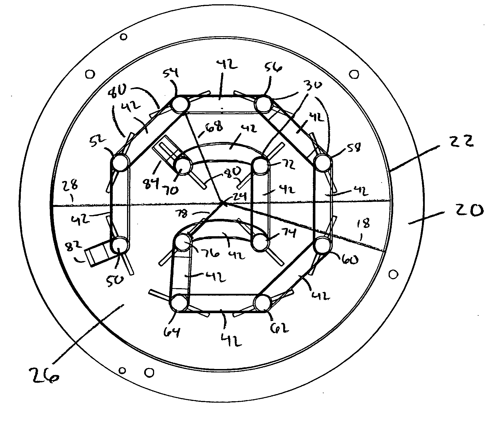
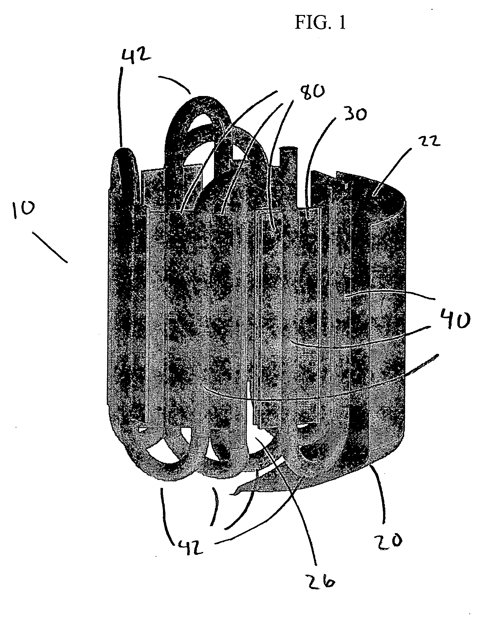
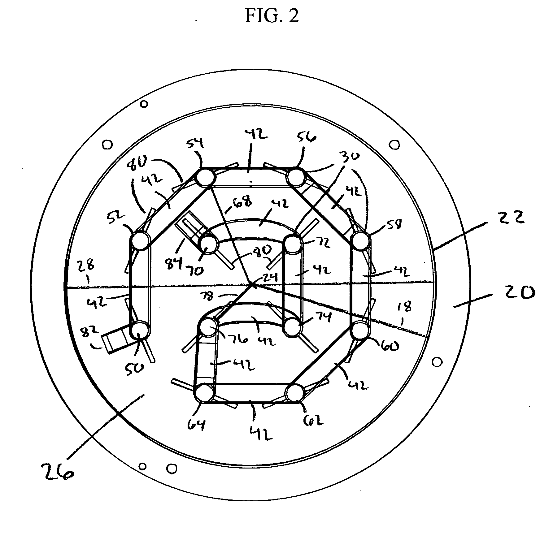
[0048] The cooling characteristics of several heating / cooling systems designs were analyzed using computer simulations with FLUENT™ computational fluid dynamics software. The simulations were based on a nominal 300 L capacity, 34″ inside diameter vessel called the 300 L Cryovessel available from Integrated Biosystems. The inner wall and heat transfer surface temperature were set at −30° C. The temperature profile of a fluid being cooled was modeled as a function of time. Three systems were modeled: 1) the prior art Integrated Biosystems design (Comparative Example 1); 2) the finned design of the present invention shown in FIGS. 1-3 (Inventive Example 2); and 3) the finless design of the present invention shown in FIGS. 4-5 (Inventive Example 3).

##ventive example 2

INVENTIVE EXAMPLE 2

[0050]FIG. 8 shows the temperature profile of the fluid for the finned design after cooling for approximately 6.5 hours. It can be seen that the present invention provides relatively small pockets of uncooled material between the heat transfer surfaces.

##ventive example 3

INVENTIVE EXAMPLE 3

[0051]FIG. 9 shows the temperature profile of the fluid for the finless design after cooling for approximately 6.5 hours. It can be seen that the present invention provides small pockets of uncooled material between the conduit portions.

[0052] In comparing the performance of the three systems, it can be seen that the prior art design leaves large pockets of uncooled fluid, and that the present invention provides much smaller pockets of uncooled fluid. It can be seen that the two embodiments of the present invention have better temperature distribution than the prior art design. Although the finless design did not perform as well as the finned design, it still showed superior cooling to the prior art design. The prior art design has large areas that cool slowly due to the distance from the heat transfer surfaces.

[0053] The computer simulations were also used to determine the liquid fraction remaining in the vessel as a function of time, to determine how quickly t...


PUM


Abstract

A method of cooling a biological material includes providing a vessel. The vessel includes a generally vertical inner wall disposed at an inner radius from a vertically disposed center axis. The generally vertical inner wall defines in part an interior volume. A medium including a biological material is provided. A plurality of heat transfer surfaces is positioned within the interior volume. Each of the plurality of heat transfer surfaces is oriented generally vertically through the interior volume. Each of the heat transfer surfaces is arranged such that it does not extend into the portion of the interior volume defined by a distance from the center axis greater than 90% of the inner radius. The medium is introduced into the vessel. A heat transfer fluid is circulated through the plurality of heat transfer surfaces. The heat transfer surfaces conduct heat out of the medium.

Description

BACKGROUND [0001] The present invention relates to a system and method for uniformly heating and cooling a material, particularly a biological material such as a biopharmaceutical product. [0002] Biological materials such as biopharmaceutical products are typically frozen for long periods of time for storage and then thawed for later use. The speed and uniformity of the freezing and thawing processes must be controlled properly. If the freezing or thawing is too slow, the active material may be subject to degradation from concentration gradients. These problems can be exacerbated by compartmentalization of the material that is freezing or thawing. Overall, uneven freezing and thawing can lead to less uniformity in the active material and challenges in properly mixing it during the freeze and thaw processes. An additional problem is that the materials best suited for contact with biological materials have relatively poor heat transfer properties. [0003] Typically, vessels used to hea...

Claims


Application Information

Patent Timeline
Patent Type & Authority Applications(United States)
IPC IPC(8): F28D7/10
CPCA61M5/44F25D31/006F28D7/08F28D7/085F28F1/14
Inventor LAM, PHILIPPESANE, SAMIR U.
Owner GENENTECH INC
Learn More