
Voltage regulation with active supplemental current for output stabilization

a voltage regulation and output stabilization technology, applied in the direction of electric variable regulation, process and machine control, instruments, etc., can solve the problem of requiring a large die area, and achieve the effect of efficient stabilizing an output voltage, substantial die area saving, and the required amount of capacitance for a decoupling capacitor

Active Publication Date: 2007-06-21
SANDISK TECH LLC
View PDF34 Cites 57 Cited by
  • Summary
  • Abstract
  • Description
  • Claims
  • Application Information

AI Technical Summary

Benefits of technology

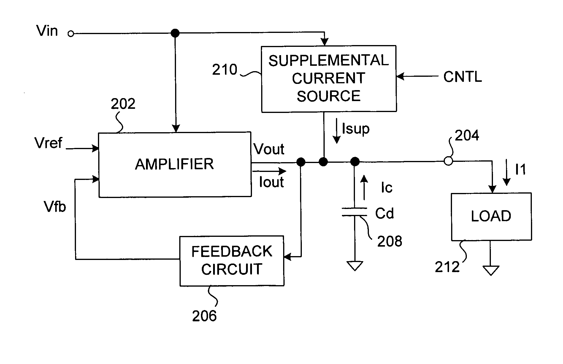
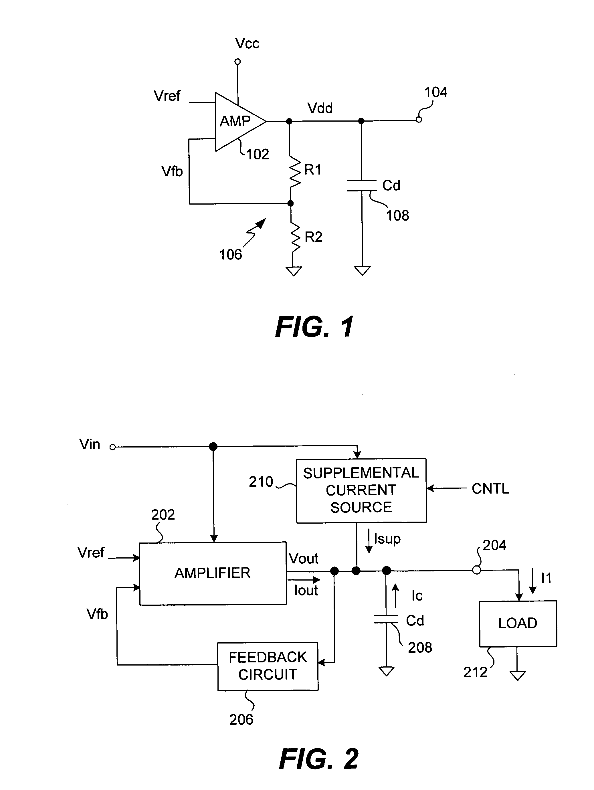
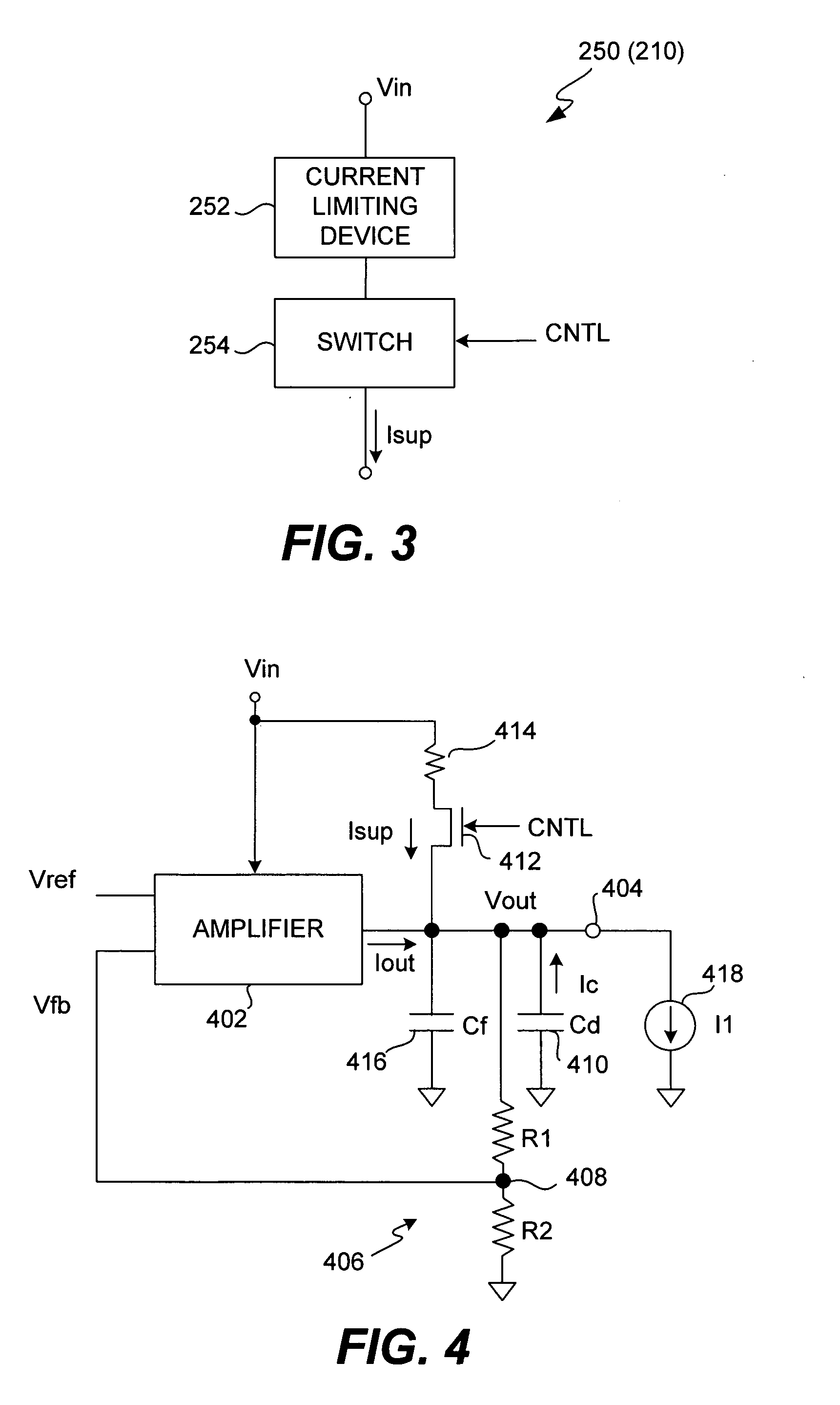
[0009] Broadly speaking, the invention relates to techniques for efficiently stabilizing an output voltage produced by a voltage regulation circuit. One embodiment of the invention pertains to a voltage regulation circuit that includes a supplemental current source that can be controllably activated to provide a supplemental current to an output terminal of the voltage regulation circuit. This supplemental current can then assist in stabilizing the output voltage level at the output terminal of the voltage regulation circuit even in the presence of high current surges by a load (i.e., electronic circuitry). Advantageously, given the availability of the supplemental current, the required amount of capacitance for a decoupling capacitor (also coupled to the output terminal of the voltage regulation circuit) can be significantly reduced. In the case of semiconductor electronic devices, the reduction in the needed capacitance yields substantial die area savings with respect to decoupling capacitors.

Problems solved by technology

Unfortunately, however, when a load coupled to the voltage regulation circuit 100 draws substantially high current levels, the decoupling capacitor 108 needs to have a relatively large capacitance to significantly stabilize the output voltage level in the presence of current surges.
However, to provide such high capacitance requires a lot of die area within a semiconductor product.

Method used


Image

  • Voltage regulation with active supplemental current for output stabilization
  • Voltage regulation with active supplemental current for output stabilization
  • Voltage regulation with active supplemental current for output stabilization

Examples


Embodiment Construction

[0023] The invention relates to techniques for efficiently stabilizing an output voltage produced by a voltage regulation circuit. One embodiment of the invention pertains to a voltage regulation circuit that includes a supplemental current source that can be controllably activated to provide a supplemental current to an output terminal of the voltage regulation circuit. This supplemental current can then assist in stabilizing the output voltage level at the output terminal of the voltage regulation circuit even in the presence of high current surges by a load (i.e., electronic circuitry). Advantageously, given the availability of the supplemental current, the required amount of capacitance for a decoupling capacitor (also coupled to the output terminal of the voltage regulation circuit) can be significantly reduced. In the case of semiconductor electronic devices, the reduction in the needed capacitance yields substantial die area savings with respect to decoupling capacitors.

[002...


PUM


Abstract

Techniques for efficiently stabilizing an output voltage produced by a voltage regulation circuit are disclosed. One embodiment pertains to a voltage regulation circuit that includes a supplemental current source that can be controllably activated to provide a supplemental current to an output terminal of the voltage regulation circuit. This supplemental current can then assist in stabilizing the output voltage level at the output terminal of the voltage regulation circuit even in the presence of high current surges by a load (i.e., electronic circuitry). Advantageously, given the availability of the supplemental current, the required amount of capacitance for a decoupling capacitor (also coupled to the output terminal of the voltage regulation circuit) can be significantly reduced. In the case of semiconductor electronic devices, the reduction in the needed capacitance yields substantial die area savings with respect to decoupling capacitors.

Description

CROSS REFERENCE TO RELATED APPLICATIONS [0001] This application is related to U.S. patent application Ser. No. ______, entitled “CHARGE PUMP REGULATION CONTROL FOR IMPROVED POWER EFFICENCY”, and filed concurrently herewith, and which is hereby incorporated by reference herein.BACKGROUND OF THE INVENTION [0002] 1. Field of the Invention [0003] The invention relates to voltage generation and, more particularly, to voltage generation internal to memory systems. [0004] 2. Description of the Related Art [0005] Memory cards are commonly used to store digital data for use with various products (e.g., electronics products). Examples of memory cards are Flash cards that use Flash type or EEPROM type memory cells to store the data. Flash cards have a relatively small form factor and have been used to store digital data for products such as cameras, hand-held computers, set-top boxes, hand-held or other small audio players / recorders (e.g., MP3 devices), and medical monitors. A major supplier o...

Claims


Application Information

Patent Timeline
IPC IPC(8): G05F1/10
CPCG05F1/575G11C5/147
Inventor PAN, FENG
Owner SANDISK TECH LLC
Learn More