
Method and apparatus for adaptive direction estimation of radio waves

a radio wave and adaptive direction technology, applied in the direction of multi-channel direction-finding systems using radio waves, instruments, pulse techniques, etc., can solve the problems of high computational load of these methods, high processing time, and high computational workload of evd (or svd) processes, so as to reduce computational load

Inactive Publication Date: 2007-06-21
FUJITSU LTD
View PDF8 Cites 8 Cited by
  • Summary
  • Abstract
  • Description
  • Claims
  • Application Information

AI Technical Summary

Benefits of technology

The present invention provides a method for estimating the directions of radio waves without the need for time-consuming processes such as EVD / SVD and with a small amount of computational load. The method can be used in conditions where the additive noise is not only temporally and spatially uncorrelated but also spatially correlated. The method uses a computationally efficient SUMWE algorithm and is capable of quickly tracking the time-varying directions in an online manner. The technical effects of the invention include reducing the amount of computational load and being able to estimate the directions of radio waves in both uncorrelated and correlated environments.

Problems solved by technology

However, when conventional subspace-based methods are used to estimate the time-varying directions in real-time, it is necessary to perform the EVD (or SVD) repeatedly, and hence the computational loads of these methods become very heavy and much processing time is required.
However, in actual array implementations, particularly when the number of array elements is large or when the time-varying directions should be estimated in an on-line manner, the EVD (or SVD) process becomes computationally intensive and time-consuming.
Therefore, applications of conventional subspace-based methods with eigendecomposition (i.e., EVD or SVD) are limited by the computational load thereof.
Therefore, when the directions of the incident waves change over time, it is not possible to estimate these DOAs quickly and with high accuracy by using conventional methods, and it becomes impossible to generate an accurate receiving / transmitting beam at the base station, correspondingly the performance of the receiving and transmitting system of the base station will degrade.
However, in the case of coherent signals, low signal-to-noise ratio (SNR) or small number of data, the performance of these methods becomes poor, and the amount of computational load required by these methods that use Least squares (LS) is large.
However, the online DOA estimation and the tracking of time-varying directions are not considered in this method.

Method used


Image

  • Method and apparatus for adaptive direction estimation of radio waves
  • Method and apparatus for adaptive direction estimation of radio waves
  • Method and apparatus for adaptive direction estimation of radio waves

Examples


first embodiment

(A) First Embodiment

[0047] This invention relates to an apparatus and method for estimating the directions of radio waves at a base station, and here the direction estimation will be explained with reference to the drawings. In the drawings, the same reference numbers will be given to parts or functions that are the same.

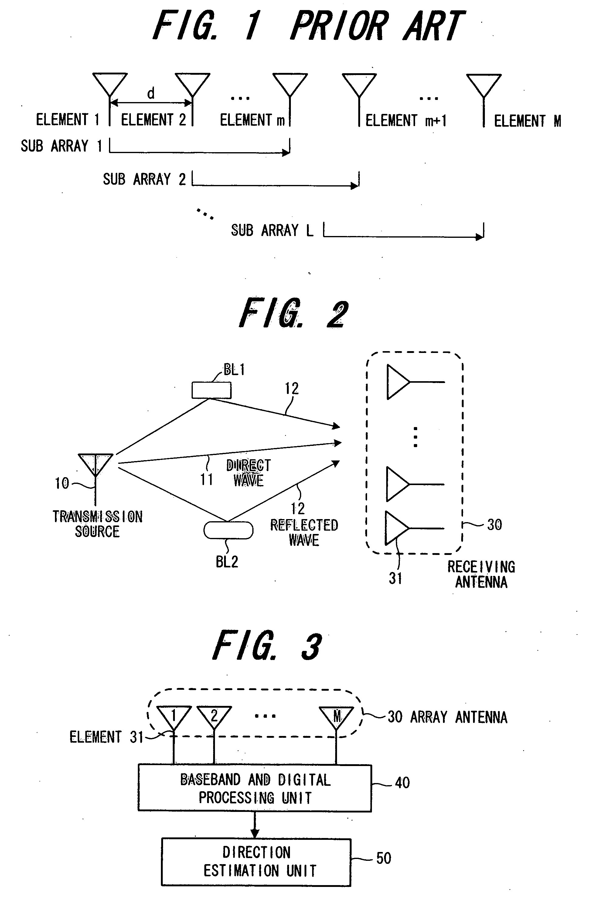
[0048]FIG. 1 is a drawing showing the construction of a ULA in which M antenna elements are located in a straight line at a distance interval of d. FIG. 2 is a drawing showing the positional relationship between the transmitting source 10 and the base station receiving antenna (array antenna) 30. In FIG. 2, the incoming signal from the transmitting source 10 impinging on the array antenna 30 is the direct wave 11, and the other incident signals are the reflected waves 12 due to reflection by buildings BL1, BL2 and the like. In the example shown in FIG. 2, two reflected waves are shown, however, hereafter, the total number of waves (coherent signals) including the d...

second embodiment

(B) Second Embodiment

[0069] In the first embodiment, four Hankel correlation matrices

φf(n)□Φf(n)□Φb(n)□Φb(n)

are formed, and each is divided into two upper and lower submatrices

Φf1(n)□Φf2(n)□Φf1(n)□Φf2(n)□Φb1(n)□Φb2(n)□Φb1(n)□Φb2(n)   A

and further two matrices Φ1(n), Φ2(n) are formed from these matrices as shown in Equation 13, then a linear operator P(n) is calculated by using these matrices Φ1(n), Φ2(n) and finally the directions of radio waves are estimated. However, it is possible to form the matrices Φ1(n) and Φ2(n) by arbitrarily using one of four groups shown in (A) above, while the first embodiment is the case of forming the matrices Φ1(n), Φ2(n) by using four groups of the above (A) as shown in (13).

(a) Embodiment using One Arbitrary Group

[0070] One arbitrary group is selected from among the four groups in (A) above, and the matrices Φ1(n), Φ2(n) are determined from one of the following equations

Φ1(n)=Φf1(n)□Φ2(n)=Φf2(n)   (25a)

Φ1(n)= Φf1(n)□Φ2(n)= Φf2(n)   (25b) ...

third embodiment

(C) Third Embodiment

[0073] The first and second embodiments are embodiments in which the directions of radio waves are estimated in an environment of temporally and spatially uncorrelated white additive noise, where the correlation between the noise wi(n)□ w□(n) included in the signals received at the ith and jth antenna elements can be expressed by the following equations

E{wi(n)wj*(n)}=□□ □□□□□

E{wi(n)wj*(n)}=0 (□≠□)

In other words, this is the case in which the length of the spatial correlation of the noise is 1. This third embodiment is an embodiment in which the length of the spatial correlation of the noise is q (□1). When the length of the spatial correlation of the noise is q, the correlation between the noise wi(n)□ w□(n) included in the signals received at the ith and jth antenna elements can be expressed by the following equations

E{wi(n)wj*(n)}≠□ (□□□□□□□)

E{wi(n)wj*(n)}=0 (□□□□□□□)

In other words, when the length of the spatial correlation of the noise is q, the noise ...


PUM


Abstract

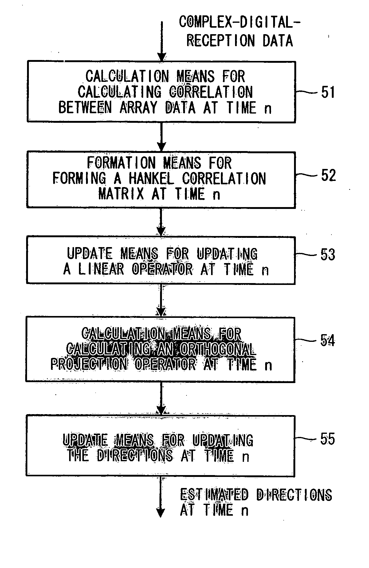
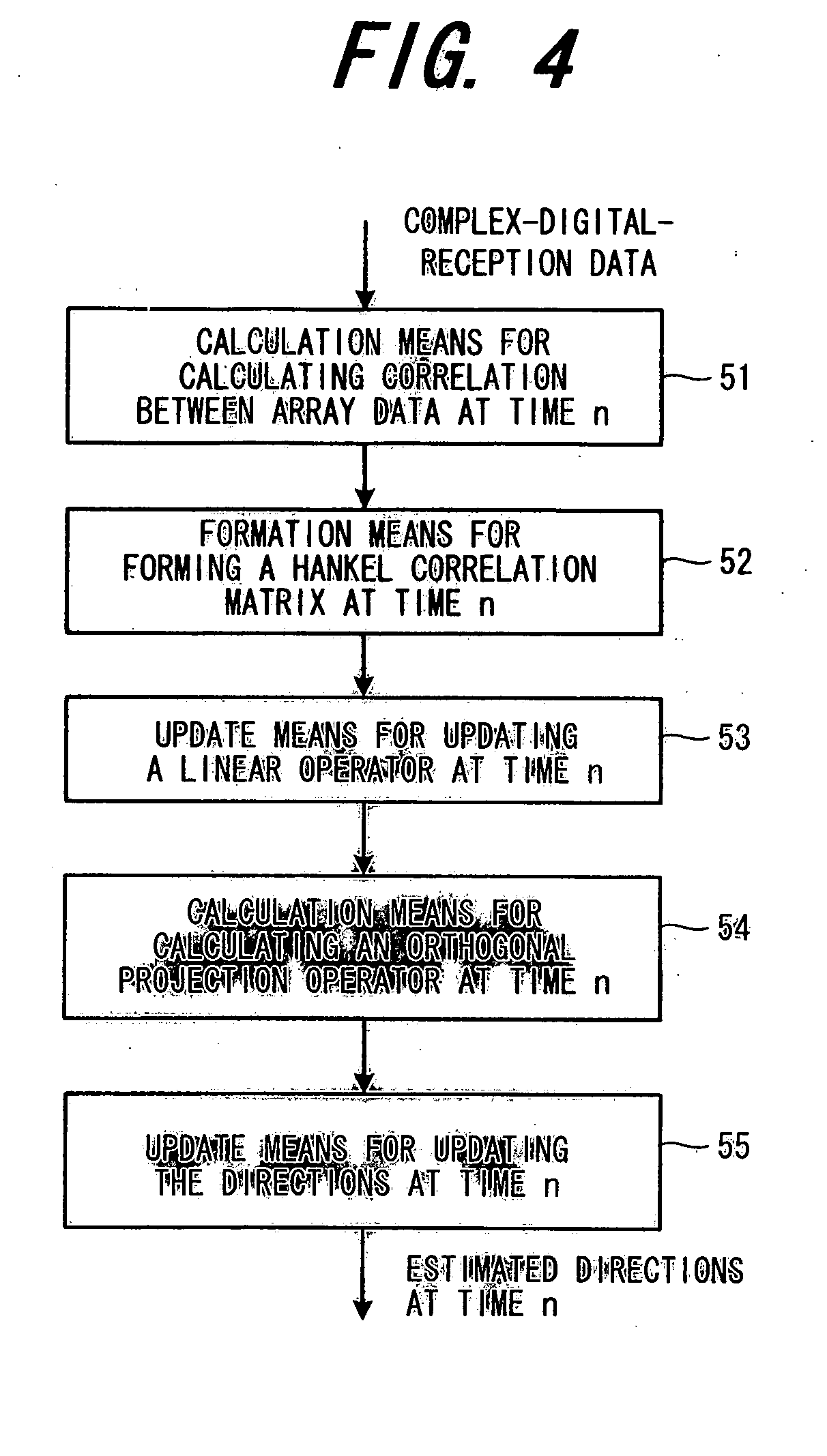
In an environment of temporally and spatially uncorrelated white additive noise, the direction estimation apparatus for coherent signals calculates (M−1) instantaneous cross-correlations between some array data, and selecting multiple pairs each of which is consisted of p instantaneous correlations from the (M−1) instantaneous cross-correlations to form a Hankel correlation matrix. Next, the apparatus divides that Hankel matrix into an upper submatrix and a lower submatrix and then calculates a linear operator at time n by using the adaptive LMS algorithm with a fixed or time-varying step-size parameter and or using the adaptive NLMS algorithm from the two submatrices. Then a noise subspace is estimated from that linear operator. Finally the directions of incident signals at time n is estimated and tracked by using that noise subspace with Newton approximation.

Description

BACKGROUND OF THE INVENTION [0001] This application is a Continuation Application of PCT Application PCT / JP2004 / 011598, filed on Aug. 12, 2004, the contents of which are herein wholly incorporated by reference. This invention relates to a method and apparatus for directions-of-arrival (DOAs) estimation of radio waves impinge on an array antenna at a base station and relates to an apparatus of base station that variably controls the beam directivity of the antenna based on the estimated directions of radio waves (also be referred to as signals from the aspect of signal processing hereafter). Further, this invention relates to a method and apparatus for estimating the directions of multiple incoming signals (mutually uncorrelated signals, or partially correlated signals, or fully correlated (i.e., coherent) signals) in an on-line manner and quickly tracking the time-varying directions. [0002] In recent years, research and development on applications of adaptive array antenna for mobil...

Claims


Application Information

Patent Timeline
Patent Type & Authority Applications(United States)
IPC IPC(8): G01S5/02G01S3/46H01Q3/26
CPCG01S3/74H04B7/08H04B7/0854H04B7/086
Inventor XIN, JINGMIN
Owner FUJITSU LTD
Learn More