Lighting device

a technology of light source and light source, which is applied in the direction of coupling device connection, lighting and heating apparatus, and with built-in power, can solve the problems of incandescent light bulbs, light sources that are very energy-inefficient, fluorescent light bulbs, and light sources that are still quite inefficient compared to solid-state light emitters, so as to reduce the temperature of light sources, reduce costs, and eliminate thermal interfaces

Active Publication Date: 2007-06-21
IDEAL IND LIGHTING LLC
View PDF99 Cites 476 Cited by
  • Summary
  • Abstract
  • Description
  • Claims
  • Application Information

AI Technical Summary

Benefits of technology

[0025] In one aspect, the present invention is directed to a lighting device which employs solid state light emitters at the chip / dice level (light emitting diodes, laser diodes, thin film electroluminescent devices, etc) which are attached to the housing of the device, the housing of the device preferably providing both the thermal and optical solution for the device. Such a design eliminates thermal interfaces (to reduce the temperature of the light source (e.g., light emitting diodes)) and reduces cost as the light emitting diode(s) or light source(s) is / are built “bottoms up” within the system to minimize cost and maximize performance. In a preferred aspect, the entire integration involves: a) light emitting diode chips mounted directly to the fixture with the required optics integrated into the fixture and the required drive electronics, in which the fixture provides the function of thermal and optical solutions, thereby reducing the complexity of many subassemblies used in conventional designs.

Problems solved by technology

It is well-known that incandescent light bulbs are very energy-inefficient light sources—about ninety percent of the electricity they consume is released as heat rather than light.
Fluorescent light bulbs are more efficient than incandescent light bulbs (by a factor of about 4) but are still quite inefficient as compared to solid state light emitters, such as light emitting diodes.
In addition, as compared to the normal lifetimes of solid state light emitters, incandescent light bulbs have relatively short lifetimes, i.e., typically about 750-1000 hours.
Fluorescent bulbs have longer lifetimes (e.g., 10,000-20,000 hours) than incandescent lights, but provide less favorable color reproduction.
Another issue faced by conventional light fixtures is the need to periodically replace the lighting devices (e.g., light bulbs, etc.).
Such issues are particularly pronounced where access is difficult (e.g., vaulted ceilings, bridges, high buildings, traffic tunnels) and / or where change-out costs are extremely high.
Light-producing device lifetime is typically much shorter, thus creating the need for periodic change-outs.
Although the development of light emitting diodes has in many ways revolutionized the lighting industry, some of the characteristics of light emitting diodes have presented challenges, some of which have not yet been fully met.

Method used


Image

  • Lighting device
  • Lighting device
  • Lighting device

Examples


Embodiment Construction

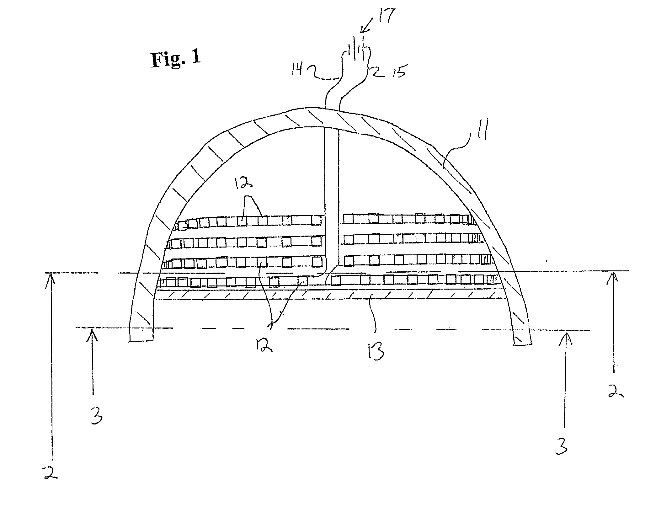
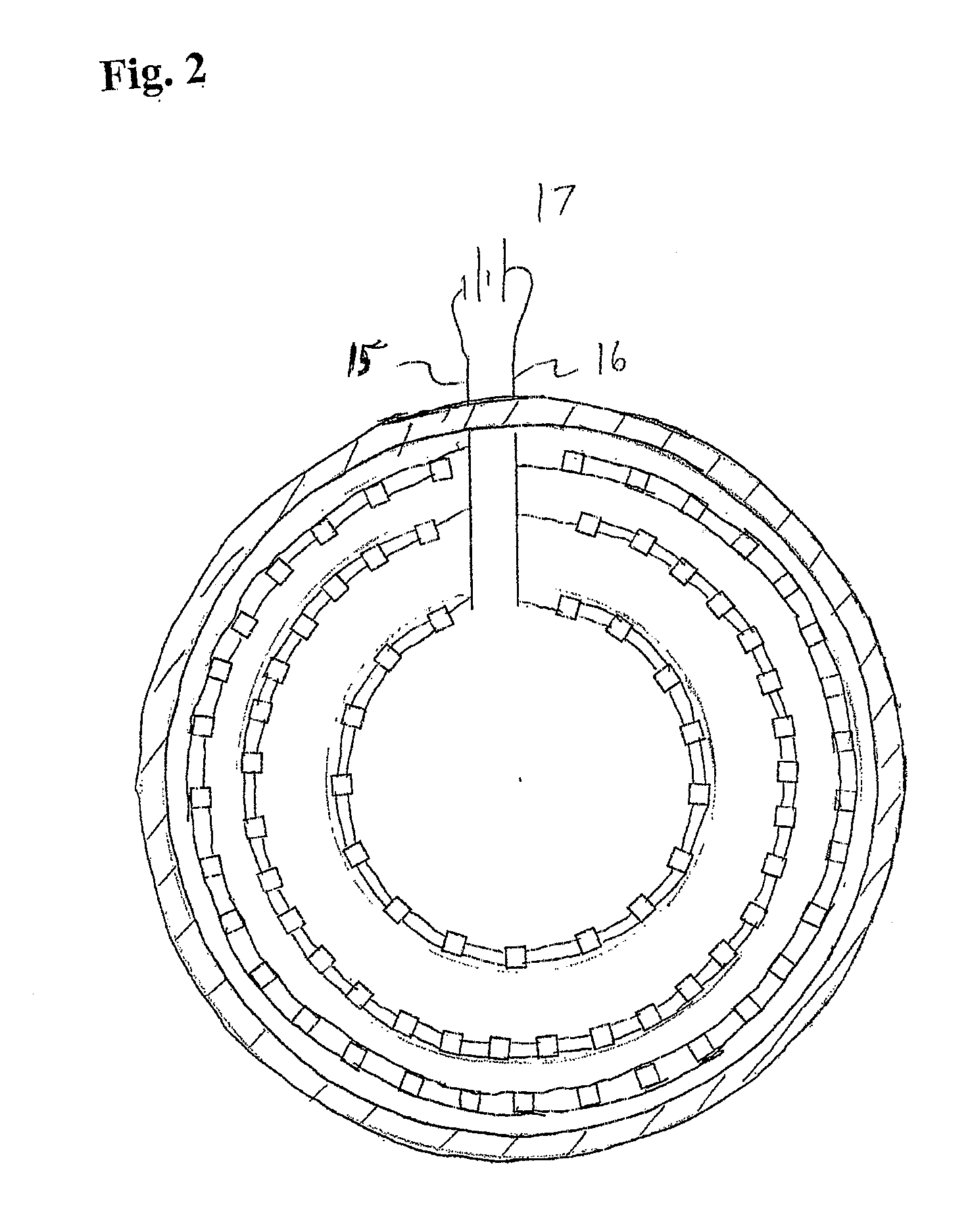
[0042] As described above, in one aspect, the present invention is directed to a lighting device which comprises a housing, at least one solid state light emitter, and conductive tracks for supplying electricity to the solid state light emitter(s). The present invention is also directed to a lighting device which comprises a housing, at least one solid state light emitter, at least one luminescent material and conductive tracks for supplying electricity to the solid state light emitter(s).

[0043] The conductive tracks can be positioned in any suitable way. For example, the conductive tracks can, if desired, be positioned on at least a first portion of the housing, and comprise at least a first positive conductive track and at least a first negative conductive track.

[0044] Each solid state light emitter can be mounted in any suitable arrangement. For example, the solid state light emitter(s) can, if desired, be mounted on the housing, in electrical contact with at least one negative...


PUM

PropertyMeasurementUnit
CRIaaaaaaaaaa
peak wavelengthaaaaaaaaaa

Abstract

A lighting device comprises, or consists essentially of, a housing, a solid state light emitter and conductive tracks. The conductive tracks are positioned on the housing and are coupleable with a power supply. The conductive tracks comprise a positive conductive track and a negative conductive track. Each of the solid state light emitters is in electrical contact with a positive conductive track and a negative conductive track. Another lighting device comprises a fixture and a solid state light emitter in which the fixture comprises conductive elements which are coupleable to at least one power supply and the solid state light emitter is mounted on the fixture. There is also provided a lighting device which provides light of an intensity which is at least 50 percent of its initial intensity after 50,000 hours of illumination.

Description

CROSS-REFERENCE TO RELATED APPLICATIONS [0001] This application claims the benefit of U.S. Provisional Patent Application No. 60 / 752,753, filed Dec. 21, 2005, the entirety of which is incorporated herein by reference.FIELD OF THE INVENTION [0002] The present invention relates to a lighting device, in particular, a device which includes one or more solid state light emitters. The present invention also relates to a lighting device which includes one or more solid state light emitters, and which optionally further includes one or more luminescent materials (e.g., one or more phosphors). In a particular aspect, the present invention relates to a lighting device which includes one or more light emitting diodes, and optionally further includes one or more luminescent materials. BACKGROUND OF THE INVENTION [0003] A large proportion (some estimates are as high as one third) of the electricity generated in the United States each year goes to lighting. Accordingly, there is an ongoing need t...

Claims


Application Information

Patent Timeline
Patent Type & Authority Applications(United States)
IPC IPC(8): F21V33/00
CPCF21S8/02F21S8/026F21S9/02F21S9/032F21V7/0008F21V3/0481F21V23/00F21V29/004F21Y2101/02F21Y2103/022F21V9/16F21V3/12F21V29/70F21Y2103/33F21Y2115/10
Inventor NEGLEY, GERALD H.VAN DE VEN, ANTONY PAULHUNTER, F. NEAL
Owner IDEAL IND LIGHTING LLC
Why Eureka
Try Eureka