Radio-controlled timepiece and method of adjusting the time kept by a radio-controlled timepiece
- Summary
- Abstract
- Description
- Claims
- Application Information
AI Technical Summary
Benefits of technology
Problems solved by technology
Method used
Image
Examples
first embodiment
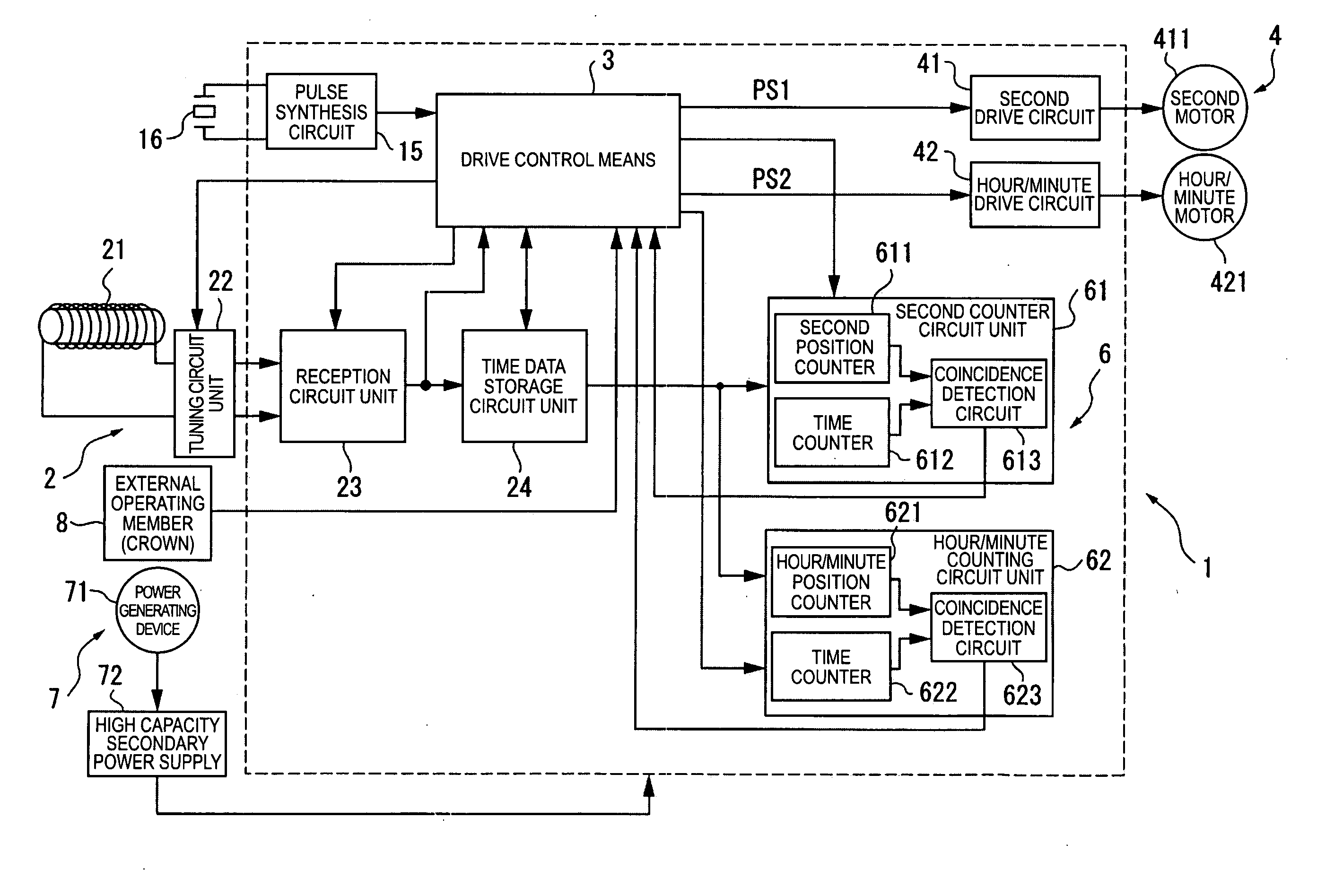
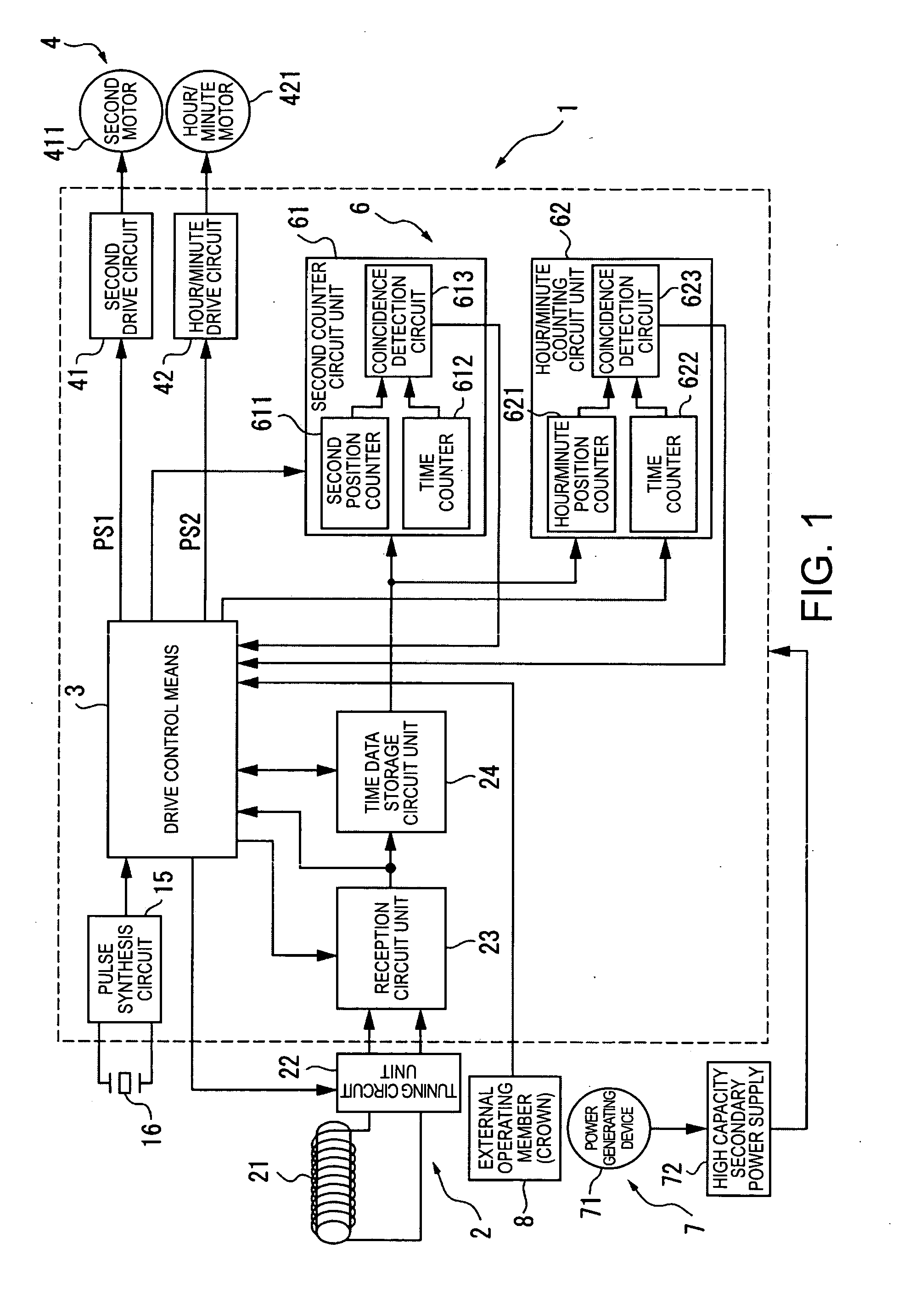
[0072]FIG. 1 is a block diagram showing the arrangement of a radio-controlled timepiece 1 as an electronic device according to a first embodiment of the invention.
[0073]The radio-controlled timepiece 1 of the present invention has the same basic arrangement as a common radio-controlled timepiece, including a time signal receiving means 2 for receiving radio frequency information containing time information (external wireless information), a drive control means 3, a mechanical drive means 4 for driving the hands, a counter means 6 for keeping time, a power supply means 7 for supplying power, and an external operating member 8 such as a crown or button.
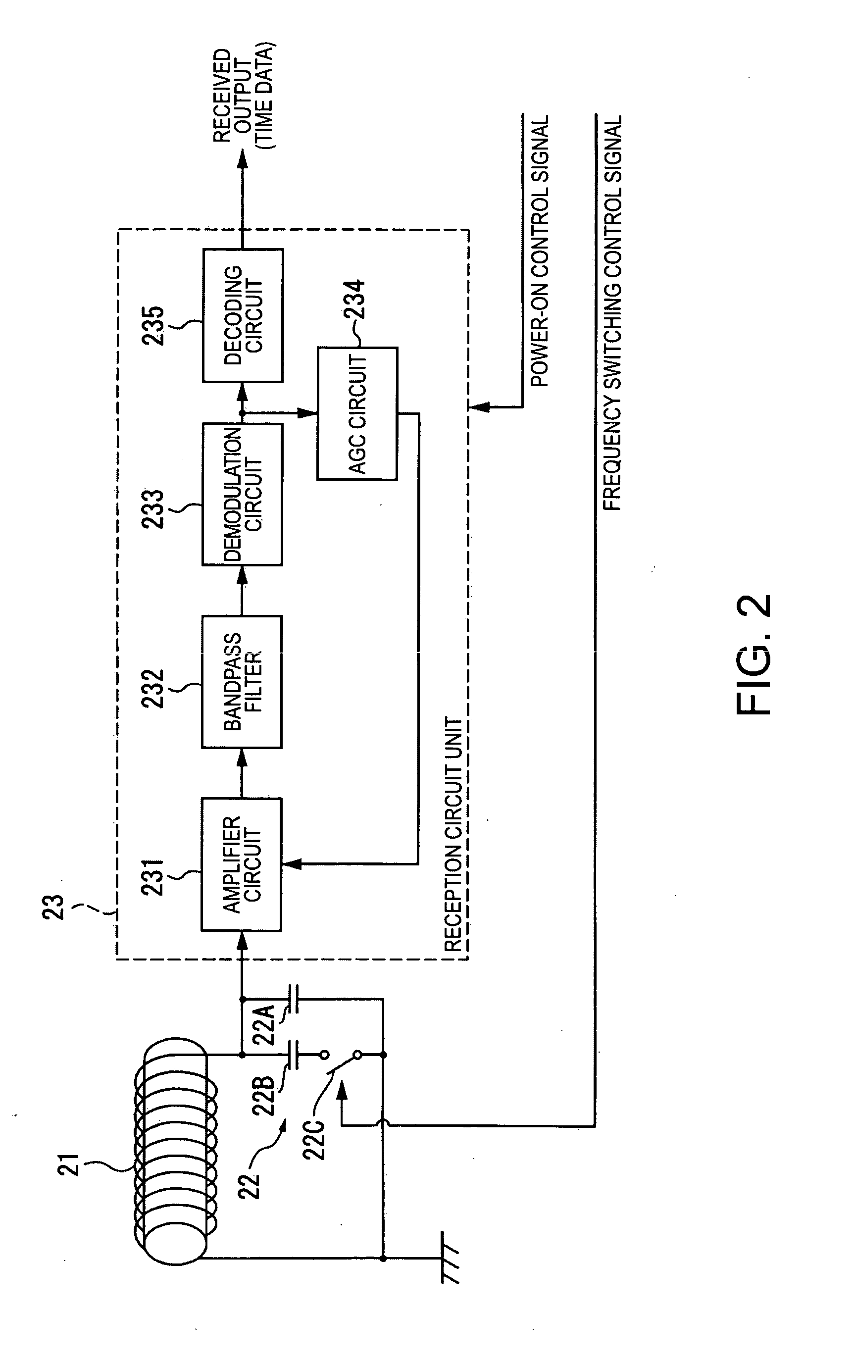
[0074]The time signal receiving means 2 has an antenna 21, a tuning circuit unit 22 such as a capacitor for tuning to the signal received by the antenna 21, a reception circuit unit 23 for processing information received by the antenna 21, and a time data storage circuit unit 24 for evaluating and storing the time data processed by the ...
second embodiment
[0163]A radio-controlled timepiece 1 according to a second embodiment of the invention is described next.
[0164]Identical or functionally similar parts in this and the previous embodiment are identified by like reference numerals, and further description thereof is omitted or abbreviated.
[0165]The radio-controlled timepiece 1 according to this second embodiment improves the pulse timing detection unit 331 so that the rising edge timing of the rectangular wave pulses can be accurately detected even when the reception signal output by the reception circuit unit 23 has a low S / N ratio and contains noise as shown in FIG. 10.
[0166]When the S / N ratio is low as shown in FIG. 10, the signal contains noise and the pulse width is narrower than in the actual time code. In the normal JJY time code the narrowest pulse width is 200 msec as shown in FIG. 5. As a result, any pulses with a width shorter than 200 msec can be dropped because they represent noise.
[0167]After detecting the rising edges o...
PUM
 Abstract
Description
Claims
Application Information
 - R&D
- Intellectual Property
- Life Sciences
- Materials
- Tech Scout
- Unparalleled Data Quality
- Higher Quality Content
- 60% Fewer Hallucinations
Browse by: Latest US Patents, China's latest patents, Technical Efficacy Thesaurus, Application Domain, Technology Topic, Popular Technical Reports.
© 2025 PatSnap. All rights reserved.Legal|Privacy policy|Modern Slavery Act Transparency Statement|Sitemap|About US| Contact US: help@patsnap.com


