Method, device and system for altering the reverberation time of a room

a technology for altering the reverberation time and rooms, applied in the direction of frequency/directions obtaining arrangements, sound producing devices, building components, etc., can solve the problems of unfavorable “boomy” reproduction of sounds in the room, loss of perceived details of music, and even speech intelligibility, and selective reduction of reverberation time at low frequencies is somewhat more difficult to implement. , the effect of reducing the reverberation time and reducing th

Active Publication Date: 2007-06-21
LARSEN
View PDF9 Cites 26 Cited by
  • Summary
  • Abstract
  • Description
  • Claims
  • Application Information

AI Technical Summary

Benefits of technology

[0021] It is a further object of the present invention to provide a device, system and method where the effect on the reverberation time can readily be changed, for instance by changing the absorption coefficient α and / or resonance frequency or frequencies of the device or system or the effective bandwidth hereof. Specifically as mentioned above an essentially on / off function of the absorbing device, i.e. a change between a very high absorption coefficient and a very low absorption coefficient within a certain specified frequency region would be desirable.
[0022] It is a further object of the present invention to provide devices and systems, which facilitate transport and storage of the devices and systems.
[0027] The system could furthermore be provided with means for measuring the reverberation time of a room in which the system is installed, thereby facilitating the appropriate set-up of the system. Such means could of course also be provided in connection with only a single device according to the invention. Furthermore the system could comprise data storage means for storing measured reverberation times and corresponding parameter settings of the device or system for later analysis and retrieval, thereby facilitating empirical improvements of the parameter choices (overall absorption area of the devices, required inflation, optimal material characteristics, etc.) of the device or system.

Problems solved by technology

Thus, low-frequency reverberation often tends to be too high compared with high-frequency reverberation, which may lead to an unacceptably “boomy” reproduction of sounds in the room, a loss of perceived details of the music and even to a deterioration of speech intelligibility. FIG. 1 shows measured reverberation time as a function of frequency of seven different rooms that may be used for live performances or reproduction of music.
Selective reduction of reverberation time at low frequencies is somewhat more difficult to implement, although a number of actual implementations have been successfully applied for many years.
Apart from the required thickness, which may exceed one meter if significant low-frequency absorption of acoustic energy is to be expected, such panels will not selectively absorb sound at low frequencies but rather exhibit a sound absorption as a function of frequency which will be fairly constant above a given lower limiting frequency—determined among other things by the thickness of the panel and the acoustic properties of the particular material being used—and decrease below this lower limiting frequency, thus not being able to provide selective low-frequency reduction of reverberation time as often required.
If the impedance is too low, then the internal losses will be too small and not enough sound energy will be absorbed.
Nevertheless such prior art absorbers suffer from a number of disadvantages, some of which are described in the following.
The sound absorption characteristics of the above prior art absorbers can not readily be altered once the absorber has been constructed.
Specifically major changes of the absorption coefficient α and / or the resonance frequency can not be accomplished by minor modifications of a given absorber.
The above-mentioned absorbers are rather bulky structures that will be difficult—or occasionally even impossible—to remove from a given room once installed.
Even though dismantling and transport to another room may be possible, great costs would be incurred by the transport due to the bulky nature of such absorbers.
Storage of a large number of rather bulky absorbers in-house could well be a problem in these cases.

Method used


Image

  • Method, device and system for altering the reverberation time of a room
  • Method, device and system for altering the reverberation time of a room
  • Method, device and system for altering the reverberation time of a room

Examples


first embodiment

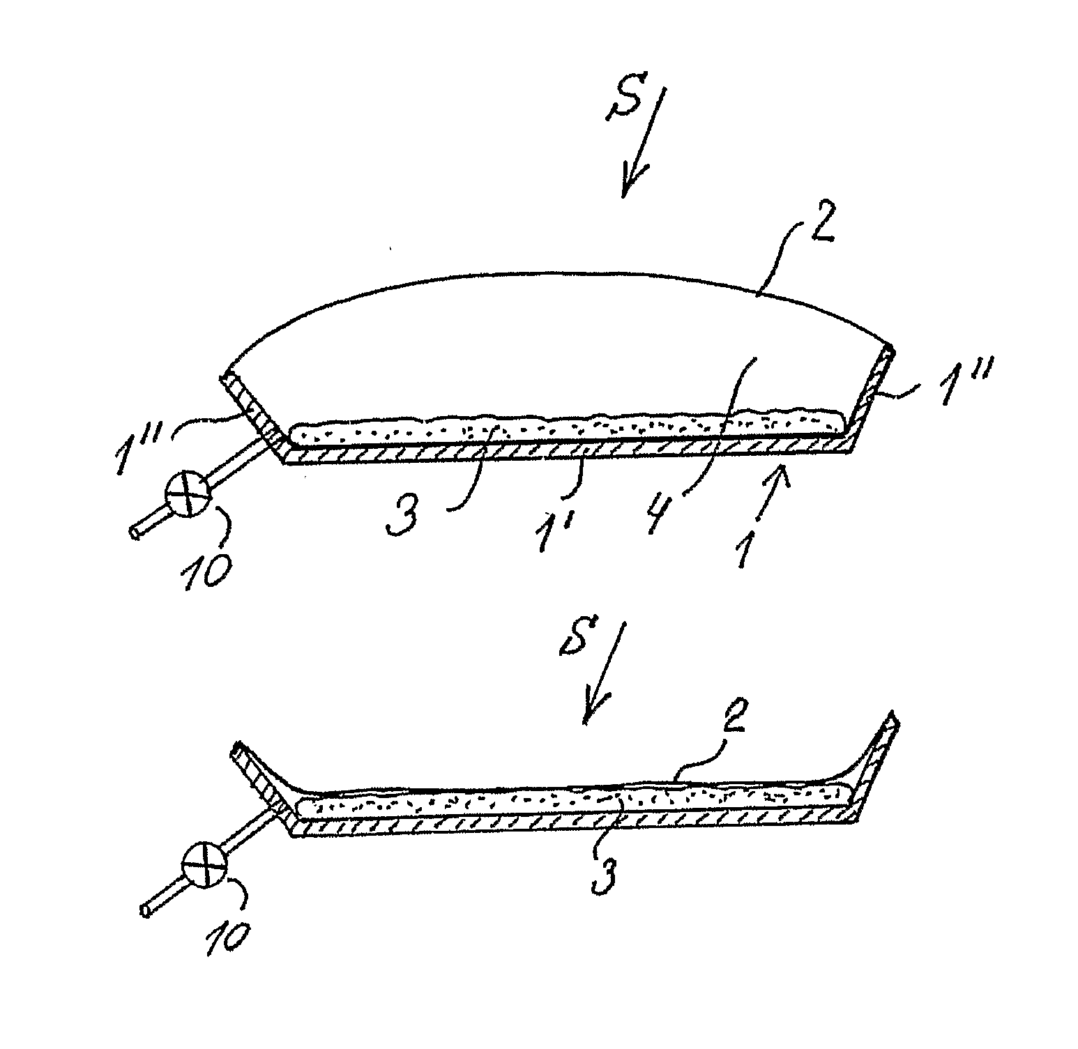
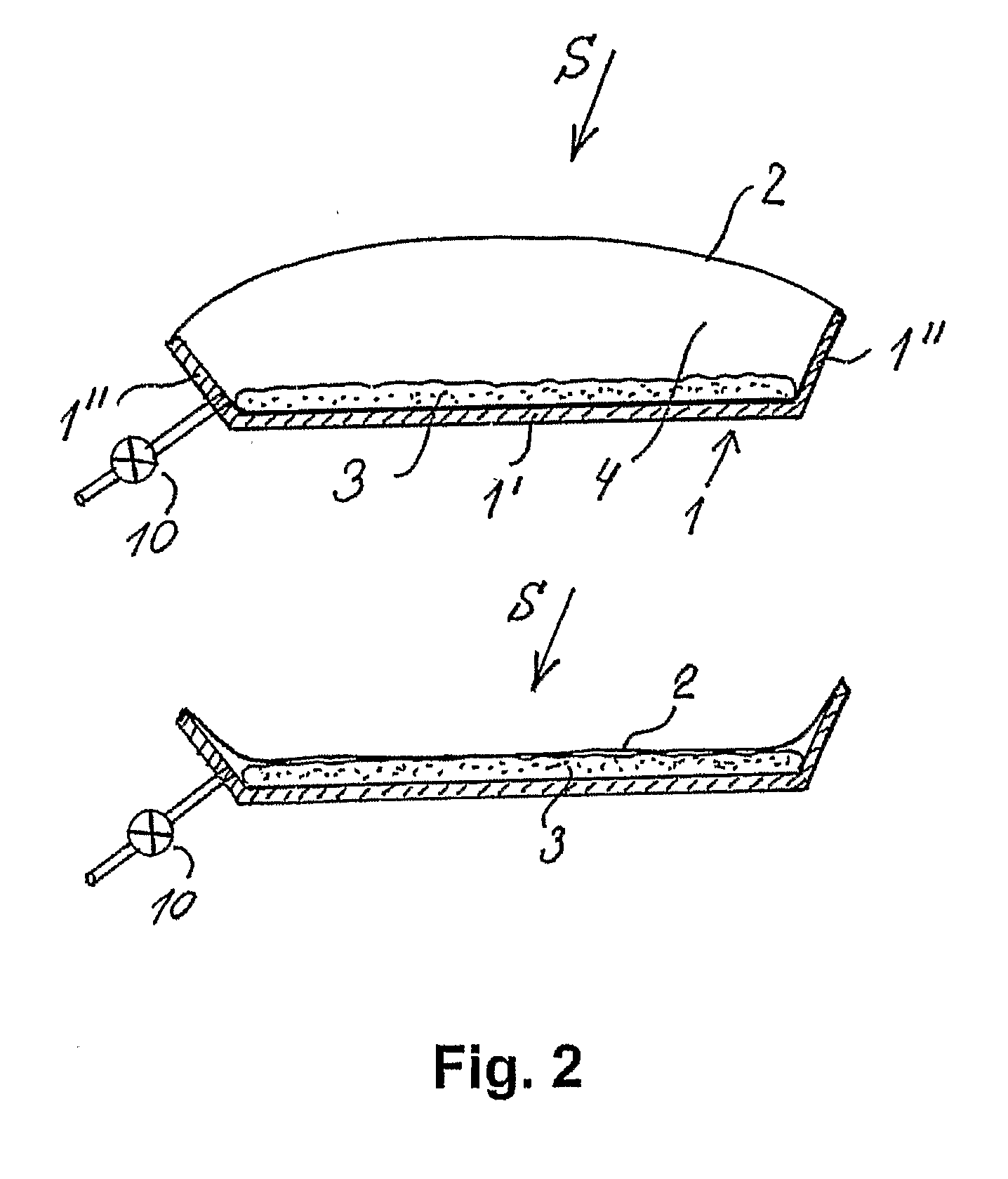
[0047] Referring to FIG. 2 there is now shown a schematic representation of a device according to the invention comprising a substantially rigid frame structure 1 comprising edge portions 1″ surrounding a central portion 1′, thus forming an open box- or tray-like support structure. Opposite the central portion 1′ and supported by the edge portions 1″ is suspended a thin, flexible membrane 2. The frame structure and the membrane define an internal cavity 4 which can be inflated / deflated with air or another suitable gas via a conduit and valve arrangement indicated by reference numeral 10. The cavity 4 may optionally be provided with a certain amount of acoustic damping material, for instance in the form of a panel 3 of porous material provided at the central portion 1′ or in the form of a suspended sheet of fabric with suitable flow resistance, suspended between the edge portions 1″ at a suitable distance from the central portion 1′. In the inflated state, acoustic energy of an incid...

second embodiment

[0051] Thus, FIGS. 4a, 4b and 4c show a schematic representation of different versions of a device according to the invention of a “mattress” configuration. As shown in FIG. 4a, the device may have the rectangular shape of a traditional mattress comprising upper and lower (not visible) substantially planar surfaces 5 bounded by edge portions 7′, 7″, thus forming an internal cavity in the mattress. Both the planar portions 5 and the edge portions 7′, 7″ are made of a suitable flexible material whereby the mattress can be brought into an inflated state as shown in FIG. 4a by the provision of air or other gas under pressure via an inlet 10 with suitable valve means. In order to maintain the inflated mattress in its proper substantially rectangular shape, cross connections 6 are provided internally between the two opposing planar surfaces 5, as is well known in itself. It is understood that other shapes of the mattress than the rectangular shape shown in FIG. 4a could also be envisaged ...

third embodiment

[0053]FIG. 5 shows a schematic representation of a device according to the invention of the collapsible type comprising an inflatable frame structure 8′, 8″ for suspension of at least one flexible membrane 9, although one of these may also be a substantially rigid panel as in the previous embodiment. The frame structure may be provided by the hollow toroidal structure 8′ and 8″ shown in FIG. 5 and inflated with air at a pressure p1 above atmospheric pressure via the inlet and valve member 11 in order to attain a relatively rigid frame structure. Suspended over this frame structure is either one or two flexible membranes 9, whereby a cavity 12 is formed between the membranes. The cavity 12 can be varied (inflated / deflated) by controlling the pressure p2 of air or other gas within the cavity, the cavity being also provided with inlet and valve means 10. Also in this embodiment, other shapes than the cylindrical shape shown may of course be envisaged without departing from the inventio...


PUM


Abstract

The invention relates to sound-absorbing devices, assemblies and systems and corresponding methods for altering the reverberation time of a room, specifically although not necessarily exclusively at low frequencies. A sound-absorbing device according to the invention comprises basically a body containing one or more cavities (4), where at least a portion of the outer surface of the body is in contact with said sound field S and where said body is inflatable / extendable and collapsible / compressible during the supply of a gas to or the removal of the gas from said at least one cavity (4), respectively, whereby the absorption coefficient (a) and / or the resonance frequency of said body can be varied, thus determining the absorption coefficient and / or the frequency region in which maximum absorption will take place.

Description

TECHNICAL FIELD [0001] The present invention relates to a method for altering the reverberation time of a room and particularly to a method for altering the reverberation time of a room in the low-frequency range. The present invention furthermore relates to sound-absorbing devices and systems of such devices used for said altering of the reverberation time of a room. The present invention furthermore relates to a room provided with such devices and / or systems, whereby the reverberation time of the room can be altered. BACKGROUND OF THE INVENTION [0002] It is well known within the art that one of the acoustic parameters that affects the perceived sound quality in a listening room, for instance a concert hall or auditorium, is the reverberation time of the room. However, the optimal reverberation time differs for various kinds of music and for speech, recommended reverberation times for rooms in which classical music is to be performed thus being in the range of 1.5 seconds to 2.0 se...

Claims


Application Information

Patent Timeline
Patent Type & Authority Applications(United States)
IPC IPC(8): H04R1/02H04R1/20H04R3/02
CPCG10K11/172
Inventor LARSEN, NIELS WERNER
Owner LARSEN
Why Eureka
Try Eureka