Fiber optic cables having at least one tether optical fiber

a fiber optic cable and optical fiber technology, applied in the field of optical fiber cables, can solve the problems of reducing the service life of the optical fiber, so as to simplify the distribution of optical fiber(s) in the optical network. the effect of tethering and quick access to the optical fiber

Inactive Publication Date: 2007-06-21
CORNING OPTICAL COMM LLC
View PDF9 Cites 16 Cited by
  • Summary
  • Abstract
  • Description
  • Claims
  • Application Information

AI Technical Summary

Benefits of technology

[0005] The present invention is directed to distribution fiber optic cables and methods for making the same. More specifically, the distribution fiber optic cables include a plurality of optical fibers disposed within a main cable body, at least one tether access location, and a cable jacket having a continuous transition to the tether access location. The tether access location includes at least one tether optical fiber that is a portion of a tether port or a portion of a tether cable. During manufacturing of the distribution cable, one of the plurality of optical fibers transitions from a first location to a second location within the cable such as from within the main cable body to the tether access location for a portion of the distribution cable, thereby becoming the at least one tether op...

Problems solved by technology

However, copper cables have drawbacks because they are large, heavy, and can only transmit a relatively limited amount of data with a reasonable cable diameter.
In other words, subscribers have a limited amount of available bandwidth due to the constraints of copper cables in the co...

Method used


Image

  • Fiber optic cables having at least one tether optical fiber
  • Fiber optic cables having at least one tether optical fiber
  • Fiber optic cables having at least one tether optical fiber

Examples


Embodiment Construction

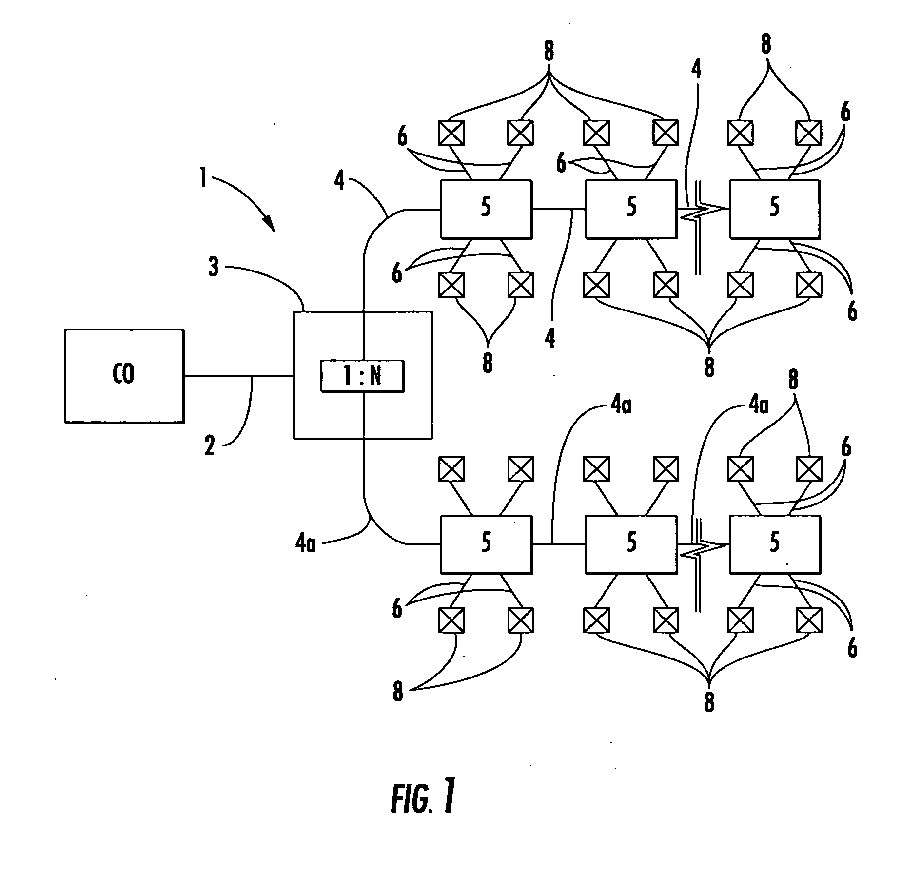
[0023]FIG. 1 schematically depicts a portion of a simplified optical fiber network 1 in an explanatory fiber to the premises (FTTP) architecture. FTTP architectures advantageously route at least one optical fiber to a premises 8, thereby providing a high bandwidth connection to the subscriber. In this case, network 1 is a centralized splitting architecture depicting fiber to the premises (FTTP), but other suitable applications such as fiber to the curb (FTTC) are possible with the concepts of the present invention. As shown, downstream from a central office CO, network 1 includes a feeder link 2, at least one fiber distribution hub (FDH) 3 having at least one 1:N splitter (not numbered), a plurality of distribution links 4,4a, a plurality of distribution terminals 5, and a plurality of drop links 6 routed to respective premises 8. In this instance, feeder link 2 is routed to the FDH where the optical fiber of feeder link 2 is split 1:N times. In this simplified network representatio...


PUM


Abstract

A distribution fiber optic cable including a plurality of optical fibers, a main cable body with some of the plurality of optical fibers being disposed within the main cable body, at least one tether optical fiber, and a cable jacket. The at least one tether optical fiber is one of the plurality of optical fibers that transitions during manufacturing from a first location within the main cable body to a tether access location for a portion of the distribution cable. The cable jacket includes a main cable body jacket and a tether access jacket portion that are connected together by a continuous transition that is applied during cable manufacturing. Thus, the craftsman may conveniently access the at least one tether optical fiber for distribution into the optical network.

Description

RELATED APPLICATIONS [0001] The present application is also related to U.S. patent application Ser. No. ______ titled “METHODS FOR MAKING FIBER OPTIC CABLES HAVING AT LEAST ONE TETHER OPTICAL FIBER” filed on even date herewith, the disclosure of which is incorporated herein by reference.FIELD OF THE INVENTION [0002] The present invention relates generally to optical fiber cables used for the distribution of optical fibers toward the subscriber. More specifically, the present invention relates to optical fiber cables having at least one tether optical fiber disposed at a predetermined tether access location for distributing the optical fiber network toward the subscriber and methods for making the cables. BACKGROUND OF THE INVENTION [0003] Communication networks are used to transport a variety of signals such as voice, video, data transmission, and the like. Traditional communication networks use copper wires in cables for transporting information and data. However, copper cables hav...

Claims


Application Information

Patent Timeline
IPC IPC(8): G02B6/00
CPCG02B6/4475
Inventor TEMPLE, KENNETH D. JR.DEAN, DAVID L. JR.GREENWOOD, JODY L.MCALPINE, WARREN W.LAIL, KEITH H.CONRAD, CRAIG M.
Owner CORNING OPTICAL COMM LLC
Why Eureka
Try Eureka