In-vivo interstitial antennas

a technology of interstitial antennas and antennas, which is applied in the field of in-vivo interstitial antennas, can solve the problems of high risk of secondary infection, inability to concentrate energy around, and high cost and recovery time of patients, and achieves good matching, low cost and high thermal efficiency.

Inactive Publication Date: 2007-06-21
POHANG UNIV OF SCI & TECH
View PDF2 Cites 71 Cited by
  • Summary
  • Abstract
  • Description
  • Claims
  • Application Information

AI Technical Summary

Benefits of technology

[0011] An objective of the present invention is to provide IVIAs in order to have good matching,

Problems solved by technology

However, such operations not only result in considerable cost and recovery time, but also expose the patients to high risk of secondary infection.
If the IVIA is not matched, the thermal energy can not be concentrated around the targeting heating area, and the microwave source may be destr

Method used


Image

  • In-vivo interstitial antennas
  • In-vivo interstitial antennas
  • In-vivo interstitial antennas

Examples


first embodiment

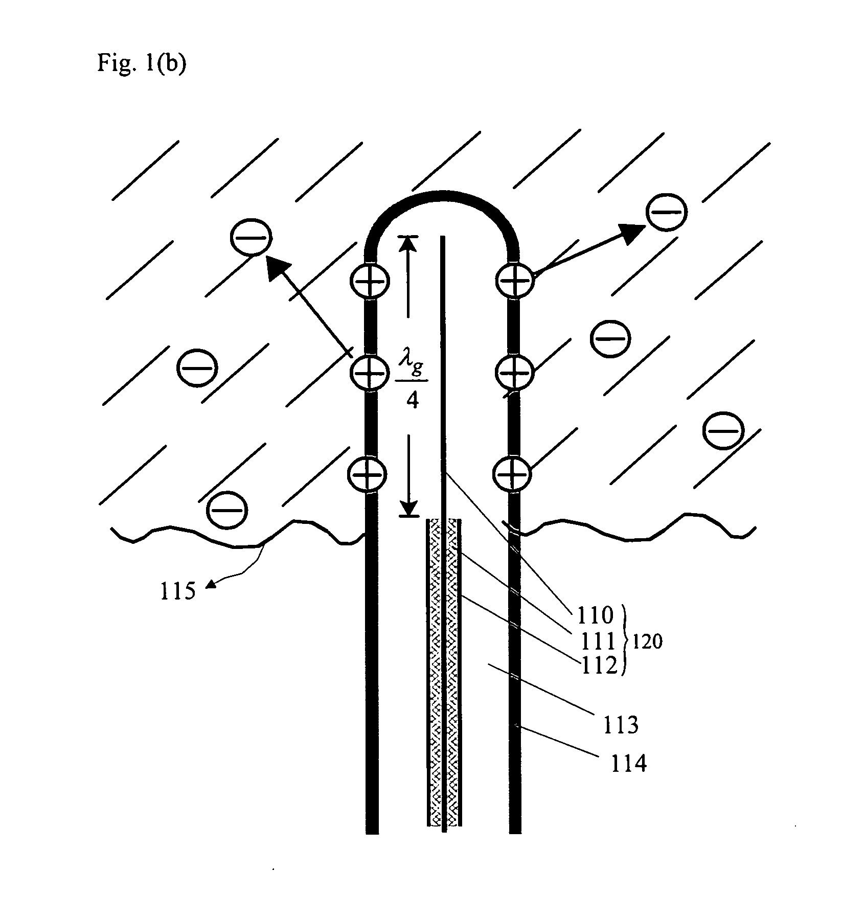
[0044]FIG. 3 shows a schematic view of an IVIA according to a first embodiment of the invention. As illustrated in FIG. 3, the IVIA comprises a coaxial cable 320 consisting of a first conductor 310, a first insulator 321 and a second conductor 322, a first capacitor 330 and a catheter 340.

[0045] Only the first conductor 310 extends less than a quarter wavelength, or, slightly longer than L and is used for applying current.

[0046] The first capacitor 330 is located around the end of the extended first conductor 310 and includes a third conductor 332 in the form of a metal tube concentrically surrounding the extended first conductor with one end at the of the first conductor closed and connected with the first conductor while the other end being open; and a second insulator 331 having a dielectric constant and filling the gap between the first and third conductors. Details on the above description will be explained in FIG. 4.

[0047] The coaxial cable 320, main material of the IVIA, c...

second embodiment

[0060]FIG. 7(a) describes an IVIA according to the second embodiment of the invention. As illustrated in FIG. 7(a), the IVIA according to the invention includes coaxial cable 620 with the first conductor 610 extending less than a quarter wavelength, or slightly longer than L, a first capacitor 630, a second capacitor 640 and a catheter 650. FIG. 7(b) compares the measured matching performance of the IVIA according to the second embodiment of the invention with the calculated one, indicating the measured matching result at 2.45 GHz is −21.9 dB.

[0061] The first conductor 610 is a conducting material and used as the central axis of the IVIA.

[0062] The coaxial cable 620 comprises a first conductor 610 having a cylindrical form and used for applying current; a second conductor 622 in the form of metal tube concentrically surrounding the first conductor and used for ground when current applied; a first insulator 621 having a dielectric constant and filling the gap between the first and ...

third embodiment

[0072]FIG. 8(a) shows a schematic diagram of an IVIA according to the third embodiment of the invention. The IVIA includes a coaxial cable 720 with a first conductor 710 extending less than a quarter wavelength, or, slightly longer than L, a first capacitor 730, a second capacitor 740, a third capacitor 750 and a catheter 760. FIG. 8(b) compares the measured matching performance of the IVIA according to the third embodiment of the invention with the calculated one, indicating the measured matching result is −24.4 dB at 2.45 GHz.

[0073] The first conductor 710 is common with the coaxial cable, the first, second and third capacitors and used as the central axis of the IVIA.

[0074] The coaxial cable 720 comprises a first conductor 710 having a cylindrical form and used for applying current; a second conductor 742 in the form of a metal tube concentrically surrounding the first conductor and used for ground when current is applied; and a first insulator 721 having a dielectric constant ...


PUM


Abstract

Disclosed are in-vivo interstitial antennas (IVIAs) for thermal treatment and deactivation of tumors by means of microwaves. An IVIA comprises a microwave monopole antenna (MMA) and a medical catheter, and the MMA is inserted into the medical catheter to form the IVIA. The MMA comprises coaxial cable and three types of capacitors. The coaxial cable consists of first and second conductors and a first insulator, and only the first conductor extends less than a quarter wavelength. The first capacitor is located around the end of the extended first conductor and includes the second insulator and the third conductor. The second and third capacitors are located between the first capacitor and the apertures of the MMAs and have about same function. Because of arbitrarily changed input impedance of the first capacitor, almost perfect matching can be achieved and desirable temperature distributions can be obtained due to the second and third capacitors.

Description

BACKGROUND OF THE INVENTION [0001] 1. Field of the Invention [0002] The present invention relates to in-vivo interstitial antennas (IVIAs). More precisely, the invention relates to IVIAs for thermal treatment and deactivation of deep-seated tumors including cancers in a human body by means of microwave. [0003] 2. Background of the Related Art [0004] Conventional surgical operations have been performed for tumors including cancers in a human body. However, such operations not only result in considerable cost and recovery time, but also expose the patients to high risk of secondary infection. To overcome the problems mentioned above, the IVIA using the microwave can be used to treat and deactivate tumors including cancers without any surgical operation. Mainly due to less expense, easy operation and short recover time, the use of the IVIAs has recently been on a dramatic increase, and many studies have been published. Details on a conventional typical IVIA will be described. [0005]FIG...

Claims


Application Information

Patent Timeline
IPC IPC(8): A61B18/04A61N1/00
CPCA61B18/18A61B18/1815
Inventor AHN, HEE-RANKIM, BUMMANLEE, KWYRO
Owner POHANG UNIV OF SCI & TECH
Why Eureka
Try Eureka