
Protection against exceeding the braking capability of remote controlled locomotives

a remote controlled, braking capability technology, applied in the direction of braking systems, vehicles, vehicles, etc., can solve the problem that the operator has failed to properly stop a remote controlled locomotive (rcl), and achieve the effect of effective braking and effective control of the remote controlled locomotiv

Active Publication Date: 2007-06-21
GE GLOBAL SOURCING LLC
View PDF20 Cites 16 Cited by
  • Summary
  • Abstract
  • Description
  • Claims
  • Application Information

AI Technical Summary

Benefits of technology

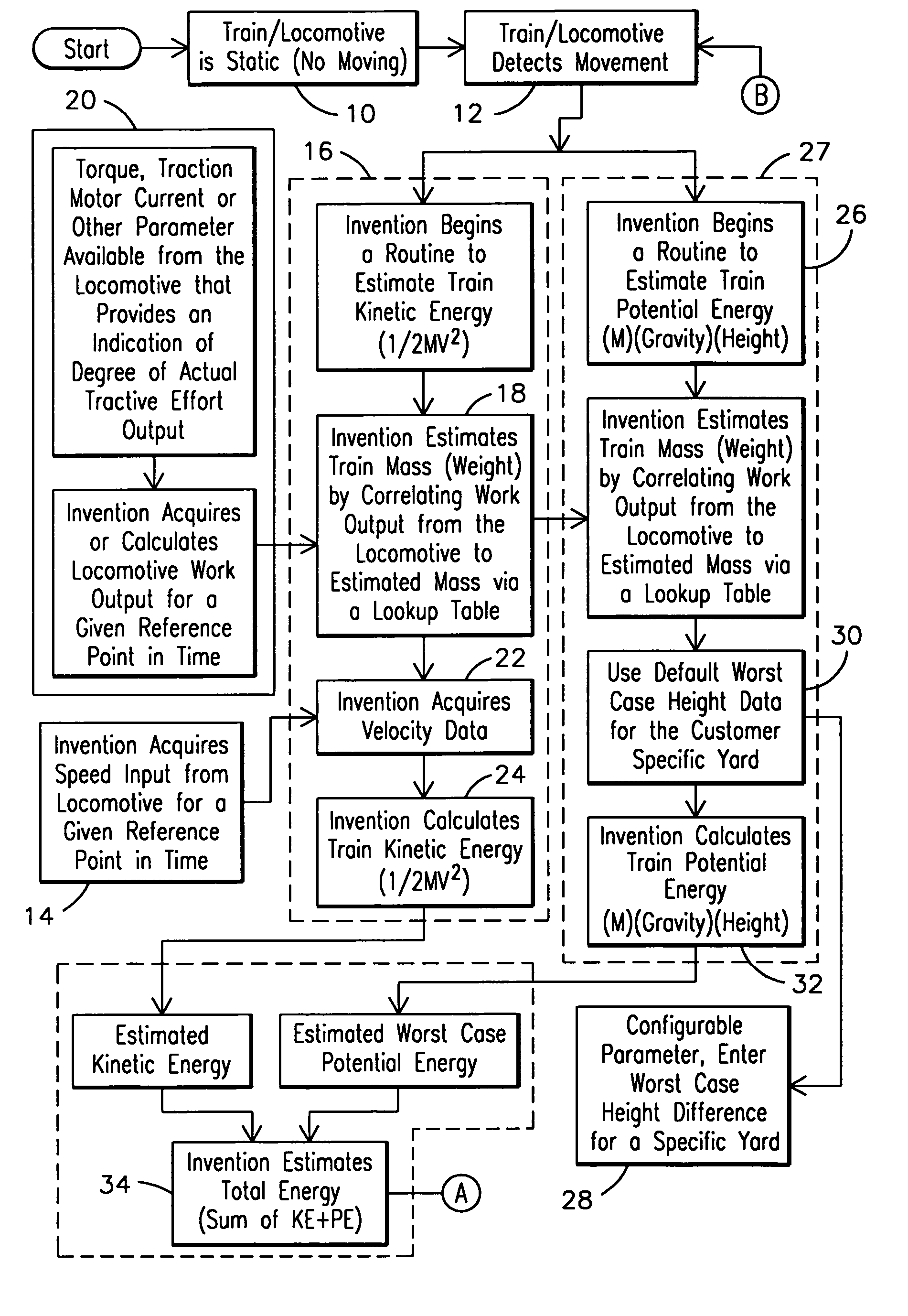
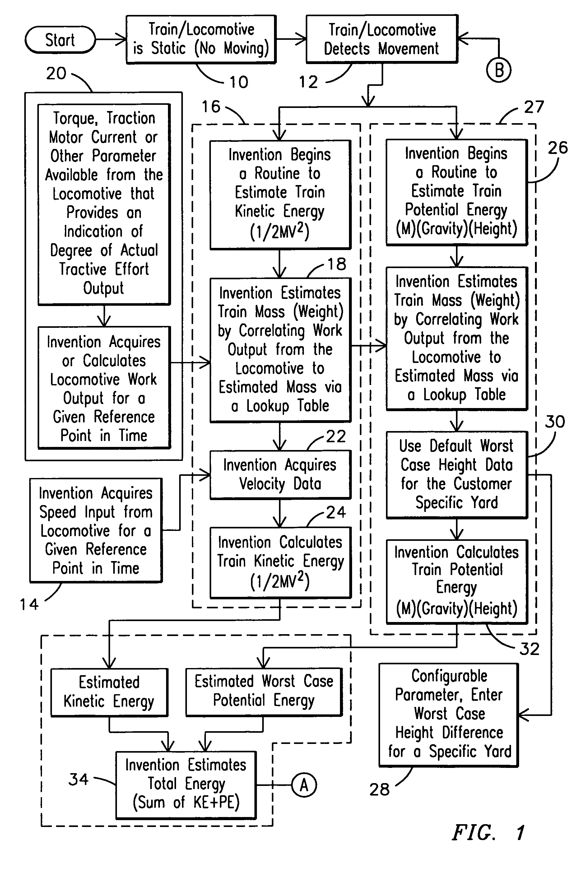
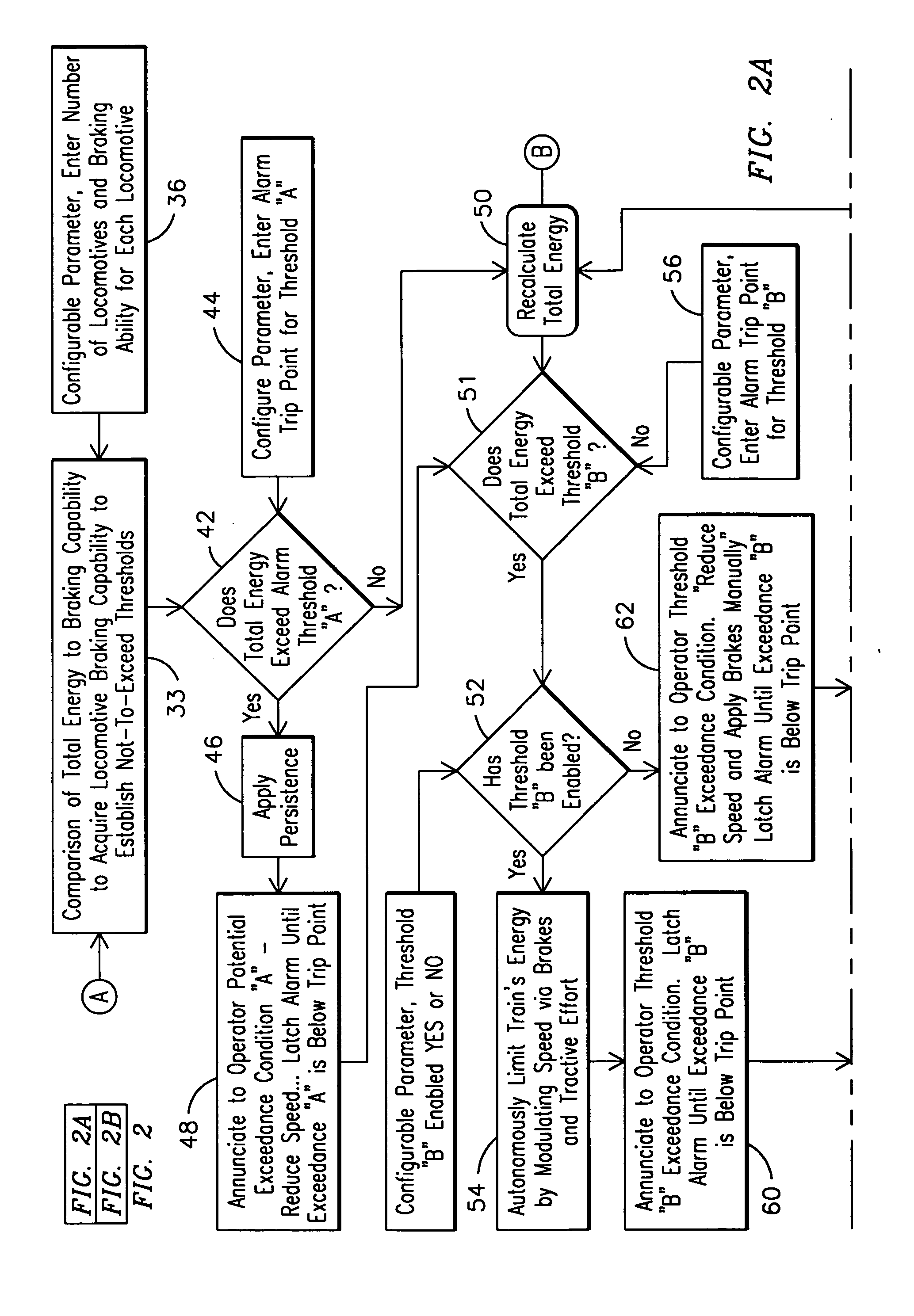
[0006] A monitoring and control system for controlling a remote controlled locomotive that is part of a train having at least one of excessive weight and operating at an excessive speed is disclosed. The system comprises a first sensor for detecting work output data from the locomotive, and a second sensor for measuring a speed of the locomotive. A processor is further disclosed for accepting work output data from the first sensor and speed of the locomotive from the second sensor so as use a program to estimate a weight of the train based on the work output data and to calculate an acceptable stopping distance based on the estimated train weight, locomotive speed, and an elevation grade. The processor factors at least a second time estimated train weight, locomotive speed, and elevation grade to determine whether the train can stop within the acceptable stopping distance.

Problems solved by technology

Events have occurred where an operator has failed to properly stop a remote controlled locomotive (RCL) because the operator did not properly consider the combined affect of weight and / or speed of the train combined with the influence of grade with respect to locomotive braking capability.
These events have resulted in train movement where the braking capability of the locomotive independent and emergency brakes are exceeded further resulting in collisions and overruns where there have been potentially catastrophic results.

Method used


Image

  • Protection against exceeding the braking capability of remote controlled locomotives
  • Protection against exceeding the braking capability of remote controlled locomotives
  • Protection against exceeding the braking capability of remote controlled locomotives

Examples


Embodiment Construction

[0011] With reference to the figures, exemplary embodiments of the invention will now be described. However, it should be noted that though the present invention describes various embodiments, namely a method, computer program, and system, those skilled in the art will readily recognize that the invention can be implemented where each embodiment may overlap. Towards this end, the exemplary embodiments discussed herein should not be viewed as individual embodiments but the intent of the elements of the present invention shall be used collectively as well, wherein the method steps may be exchanged with computer software elements and / or with hardware elements.

[0012] Furthermore, it should be realized that the present invention may be completely autonomous or may include a mixture of autonomous action and manual action. Towards this end, those skilled in the art will recognize that technology used in the present invention is predictive in nature and is useful in providing an early esti...


PUM


Abstract

A method for controlling a remote controlled locomotive that is part of a train to insure effective braking, the method including calculating an estimated total energy of a train, calculating a threshold representing a predetermined braking capability limit of the locomotive, determining whether the estimated total energy is at least one of approaching and exceeding the threshold, and decreasing a velocity of the train until the threshold is at least one of no longer being approached and is no longer exceeded.

Description

FIELD OF INVENTION [0001] This invention relates generally to the field of rail transportation and, more particularly, to a method, computer program, and system for effectively controlling a remote controlled locomotive that is part of a train. BACKGROUND OF THE INVENTION [0002] The remote control operation of a locomotive is useful for allowing a ground-based operator to control the locomotive from trackside when the locomotive is in a switching yard. A remote control unit typically includes one or more handheld transmitting units for communicating with a controller on the locomotive. This type of system permits an operator to perform such operations as coupling and uncoupling cars from the train the locomotive is connected to, while retaining control over the speed of the locomotive, and thus the train, by manually regulating the throttle and brake systems. [0003] Events have occurred where an operator has failed to properly stop a remote controlled locomotive (RCL) because the op...

Claims


Application Information

Patent Timeline
IPC IPC(8): G06F17/00
CPCB60T17/228B60T7/126B60T7/16B60T13/662B61L3/127B61L15/0062
Inventor PLAWECKI, DANIEL W.BRAND, JOHN W.
Owner GE GLOBAL SOURCING LLC
Learn More