Storage controller, and method of controlling storage controller

a storage controller and controller technology, applied in the direction of instruments, liquid/fluent solid measurement, sustainable buildings, etc., can solve the problems of not being able to quickly access saved data, reducing the energization time in each of the hard disk drives, and not being able to use sata disks as reliabl

Inactive Publication Date: 2007-06-21
HITACHI LTD
View PDF10 Cites 71 Cited by
  • Summary
  • Abstract
  • Description
  • Claims
  • Application Information

AI Technical Summary

Benefits of technology

[0011] The present invention is contrived in view of above problems, and an object thereof is to provide a storage controller and a method of controlling the storage controller in which the energization time for the storage devices can be reduced to improve the reliability of the storage controller. Another object of the present invention is to provide a storage controller and a method of controlling the storage controller in which supply of the power of each storage device is controlled on the basis of the access status of a physical storage device, and a logical storage device is moved between the physical storage devices having different power supply modes on the basis of the access status of the logical storage device, whereby the energization time in each of the storage devices can be reduced, the reliability of the storage controller can be improved, and electricity consumption is reduced. Yet another object of the present invention will be apparent from the description of embodiments provided hereinafter.
[0019] For example, the relocation plan creation portion can create a plan for locating the logical storage devices having frequently-accessed data in the physical storage devices that are energized constantly or for a long period of time. Moreover, the relocation plan creation portion can create a plan for locating the logical storage devices having infrequently-accessed data in the physical storage devices that are energized only when necessary.
[0021] By relocating the logical storage devices, the logical storage devices are brought together in the physical storage devices that are set to a predetermined power supply mode, for each type of the access status (access pattern). For example, the frequently-accessed logical storage devices are brought together in the physical storage devices that are energized for relatively long period of time, and the infrequently-accessed logical storage devices brought together in the physical storage devices that are energized only when necessary. Therefore, it is possible to minimize unwanted power supply to the physical storage devices, to reduce the possibility that the storage devices fail, to improve the reliability of the storage controller, and to reduce electricity consumption on the storage controller.
[0024] In an embodiment of the present invention, the power supply mode setting portion calculates an access frequency to each of the physical storage devices on the basis of the access information about each of the physical storage devices. The power supply mode setting portion sets a long-time energization mode, where a power supply time period is relatively long, for each of the storage devices configuring the physical storage device in which the calculated access frequency is relatively high, and sets a short-time energization mode, where a power supply time period is relatively short, for each of the storage devices configuring the physical storage device in which the calculated access frequency is relatively low.
[0027] In an embodiment of the present invention, the short-time energization mode is set as a mode of supplying power only when access is requested from the host device.
[0030] In an embodiment of the present invention, the power control portion stops supply of power to each of the storage devices configuring a physical storage device which is not accessed for a predetermined amount of time or longer, on the basis of the access information about each of the physical storage devices.

Problems solved by technology

However, when using the tape device, a magnetic tape stored with desired data needs to be carried away from a storehouse and set in a reader, thus it is not possible to promptly access the saved data.
However, the SATA disks are not as reliable as the FC (Fiber Channel) disks with the FC interfaces, thus there is room for improvement in the SATA disks in terms of the availability of the storage controller.
Therefore, simply switching the powers ON and OFF the disk drives individually is unlikely to reduce the energization time in each of the hard disk drives.
The conventional technologies do not sufficiently consider the characteristics or arrangement of the data stored in the disk drives, thus it is difficult to reduce the energization time (operating time) in the disk drives.

Method used


Image

  • Storage controller, and method of controlling storage controller
  • Storage controller, and method of controlling storage controller
  • Storage controller, and method of controlling storage controller

Examples


embodiment 1

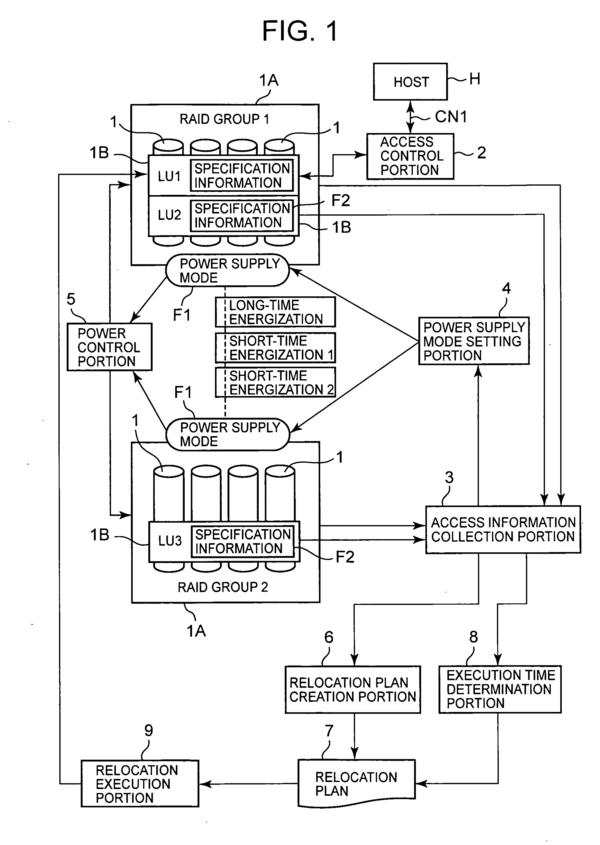
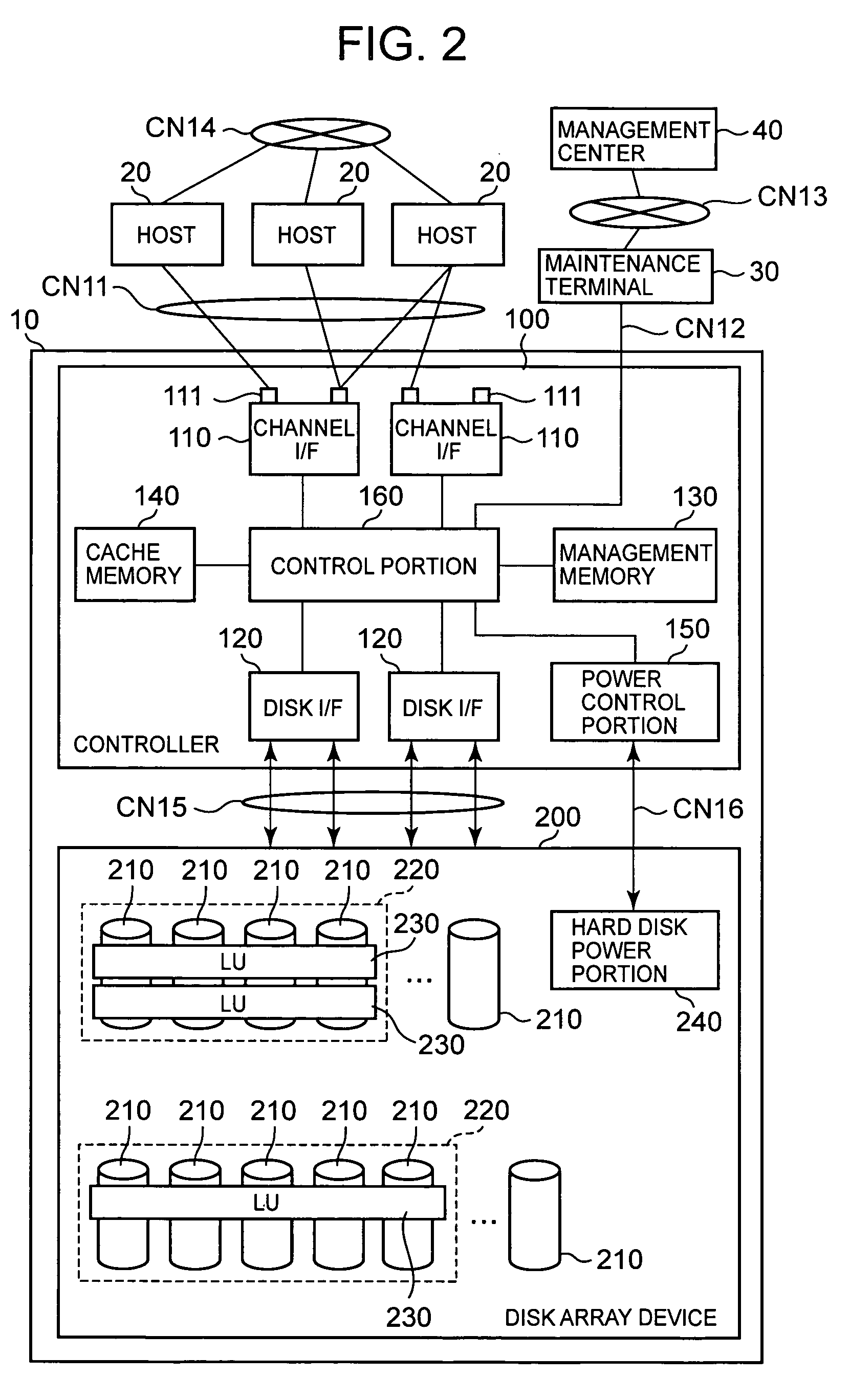
[0096] The embodiments of the present invention are described in detail. To describe the relationship between the present embodiment and FIG. 1 first, the host H in FIG. 1 corresponds to a host 20 in FIG. 2, the disk drive 1 in FIG. 1 corresponds to a disk drive 210 in FIG. 2, the RAID group 1A in FIG. 1 corresponds to a RAID group 220 in FIG. 2, the logical volume 1B in FIG. 1 corresponds to a logical volume 230 in FIG. 2, and the power control portion 5 in FIG. 1 corresponds to a power control portion 150 and hard disk power portion 240 in FIG. 2. Other control functions shown in FIG. 1 are realized by a controller 100 as described hereinafter.

[0097] First of all, a network configuration of a storage system comprising a storage controller 10 is described. The storage controller 10 is connected to one or a plurality of hosts 20 via a communication network CN11. Further, the storage controller 10 is connected to a maintenance terminal 30 via a communication network CN12. The mainte...


PUM


Abstract

The present invention controls supply of power to a storage device on the basis of an access status, moves a logical storage device between physical storage devices having different power supply modes, reduces energization time, and improves the reliability. A relocation plan creation portion creates a relocation plan by disposing a logical volume with high access frequency in a RAID group which is in a long-time energization mode, disposing a logical volume with moderate access frequency in a RAID group which is in a first short-time energization mode, and disposing a logical volume with low access frequency in a RAID group which is in a second short-time energization mode. An execution time determination portion determines an execution time for executing the relocation plan, on the basis of the access frequency to the RAID groups. The volumes with higher access frequency are disposed in the RAID group in which the power supply time is long, and the volumes with lower access frequency are disposed in the RAID group in which the power is supplied in an on-demand fashion.

Description

CROSS-REFERENCE TO RELATED APPLICATIONS [0001] This application relates to and claims priority from Japanese Patent Application No. 2005-362734 filed on Dec. 16, 2005, the entire disclosure of which is incorporated herein by reference. BACKGROUND OF THE INVENTION [0002] The present invention relates to a storage controller and a method of controlling the storage controller. [0003] The storage controller is constructed such that the storage devices such as hard disk drives and the like are disposed therein in the form of an array, and provides a host computer (sometimes referred to as “host” hereinafter) with a storage region based on, for example, RAID (Redundant Array of Independent Disks). At least one logical volume (logical storage device) is formed on a physical storage region (physical storage device) which is provided by a group of storage devices, and the host is provided with this logical volume. The host reads and writes data with respect to the logical volume by transmitt...

Claims


Application Information

Patent Timeline
Patent Type & Authority Applications(United States)
IPC IPC(8): G06F12/16
CPCG06F3/0634G06F3/0647G06F3/067Y02B60/1217Y02B60/1246G06F1/3203G06F1/3268G06F3/0616G06F3/0625G06F3/0631Y02D10/00
Inventor WATANABE, YASUOEGUCHI, YOSHIAKI
Owner HITACHI LTD
Why Eureka
Try Eureka