
Method of displaying progress bar and television receiver using the same

a technology of progress bar and television receiver, which is applied in the field of television receivers, can solve the problems of user having to perform a tedious search of the content of stored streams, encumbering and difficulty in discriminating stored broadcast programs, so as to facilitate the use of time-shift function and facilitate user's content discrimination.

Inactive Publication Date: 2007-06-21
LG ELECTRONICS INC
View PDF5 Cites 48 Cited by
  • Summary
  • Abstract
  • Description
  • Claims
  • Application Information

AI Technical Summary

Benefits of technology

[0012]Another object of the present invention is to provide a method of displaying a progress bar and to a television receiver using the same, which facilitates a user's discrimination of the content of a stored stream of a broadcast signal received in real time.
[0013]Another object of the present invention is to provide a method of displaying a progress bar and to a television receiver using the same, which facilitates a use of a time-shift function for a stored stream of a broadcast signal.

Problems solved by technology

In the contemporary television receiver as above, however, the progress bar only indicates the storage status (data storage quantity) of the broadcast signal, so that, if different broadcast programs are consecutively stored in the storage area, it is difficult to discriminate the stored broadcast programs, thereby encumbering use of the time-shift function.
The discrimination is particularly difficult if broadcast channels are changed while storing a broadcast signal for executing the time-shift function or if playback of a specific program within a long-running data stream is desired, so that the user is forced to perform a tedious search of the content of stored streams.

Method used


Image

  • Method of displaying progress bar and television receiver using the same
  • Method of displaying progress bar and television receiver using the same
  • Method of displaying progress bar and television receiver using the same

Examples


Embodiment Construction

[0027]Reference will now be made in detail to exemplary embodiments of the present invention, examples of which are illustrated in the accompanying drawings. Wherever possible, like reference designations will be used throughout the drawings to refer to the same or similar parts.

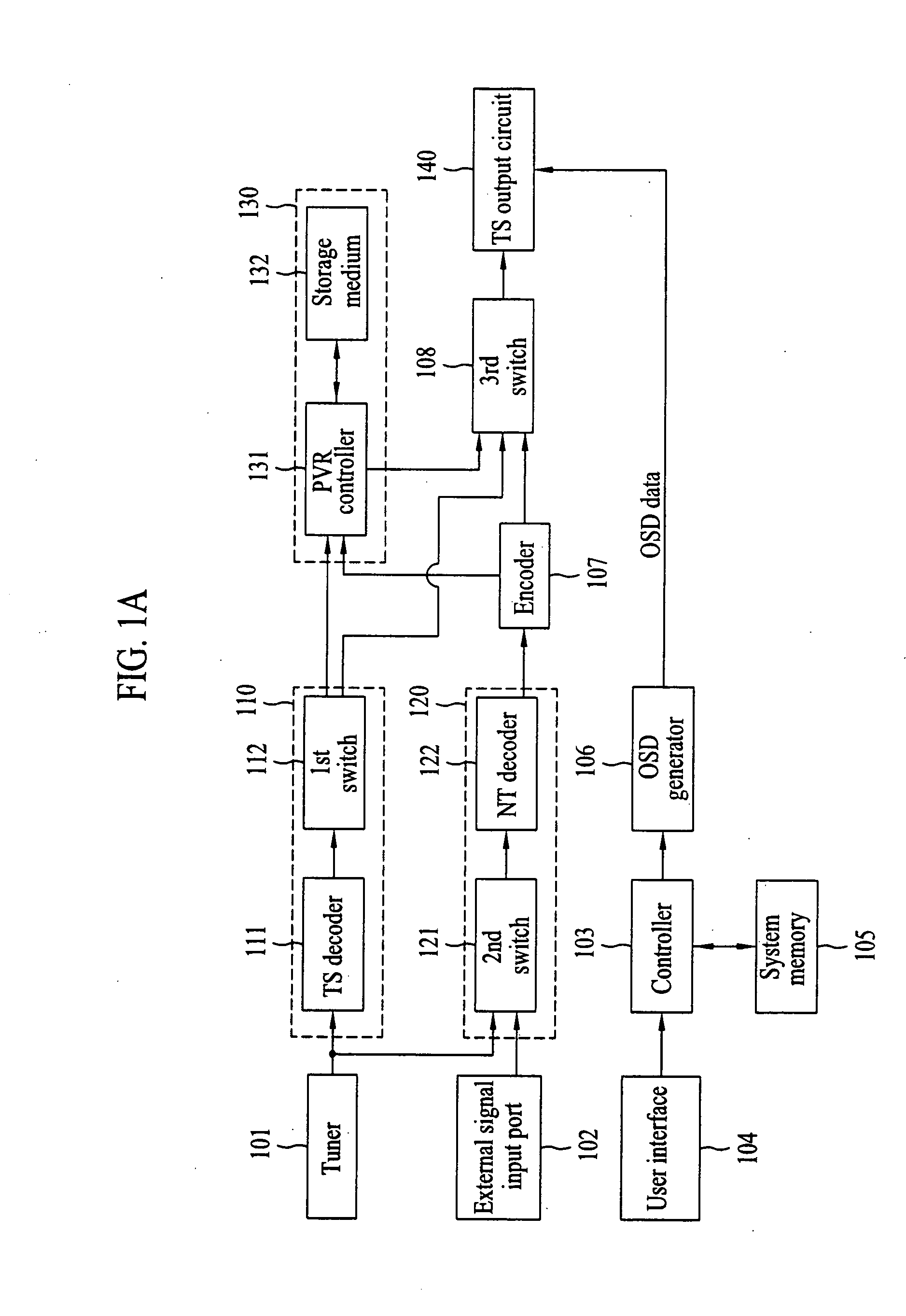
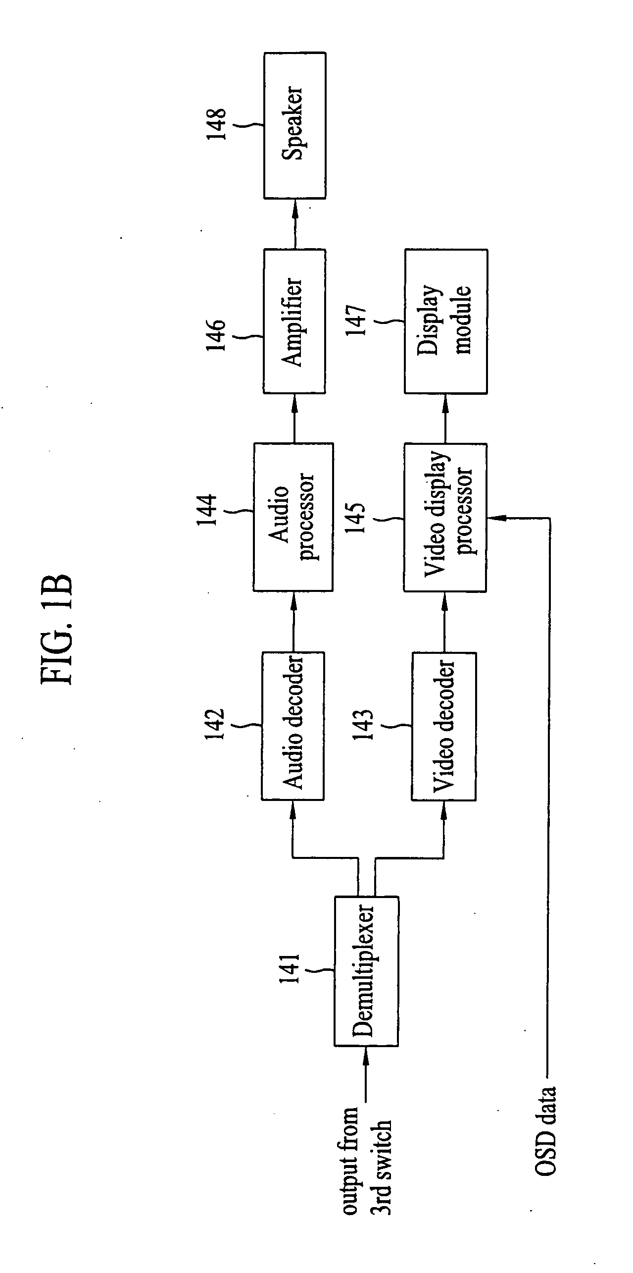
[0028]The present invention is applicable to video apparatuses capable of storing a video signal received from various input sources such as a tuner or a peripheral device. For example, a tuner 101 may be provided to receive a user-specified broadcast signal by tuning among available terrestrial or cable broadcast signals to thereby provide a digital input signal or an analog input signal, and a peripheral device such as a digital camcorder or DVD player may be connected to a television receiver via an external signal input port 102 for supplying a video signal to be stored. The video signal input to a video apparatus adopting the present invention is encoded to provide a data stream configured in a transpor...


PUM


Abstract

A method of displaying a progress bar and to a television receiver using the same, enables a plurality of stored broadcast programs to be identified according to broadcast channel or broadcast program. The method includes steps of pre-storing, in a memory of the television receiver, a plurality of display characterization indicators, the pre-stored indicators being arranged in a table of the memory to correspond to a plurality of broadcast program characteristics of at least one broadcast signal; storing, in a personal video recorder of the television receiver, a broadcast signal received by the television receiver in real time; periodically extracting broadcast program markers from the received broadcast signal, each marker being indicative of at least one of the plurality of broadcast program characteristics; and displaying the progress bar according to the extracted broadcast program markers, the displayed progress bar being superposed on a display of the broadcast signal. Each currently extracted broadcast program marker is compared with the broadcast program marker immediately preceding the currently extracted broadcast program marker, to determine whether there is a match between any adjacent two of the extracted broadcast program markers. If the compared broadcast program markers match, display of the progress bar proceeds using a first display characterization indicator, and if the compared broadcast program markers do not match, display of the progress bar proceeds using a second display characterization indicator.

Description

[0001]This application claims the benefit of Korean Patent Application No. 10-2005-0123891, filed on Dec. 15, 2005, which is hereby incorporated by reference as if fully set forth herein.BACKGROUND OF THE INVENTION[0002]1. Field of the Invention[0003]The present invention relates to television receivers, and more particularly, to a method of displaying a progress bar and to a television receiver using the same.[0004]2. Discussion of the Related Art[0005]A television receiver provided with a personal video recorder includes a storage medium such as a hard disc drive for recording (storing) and reproducing video signals including their associated audio components. The stored signals are digital video signals that are input to the television receiver and may be broadcast signals received from a broadcast station or other signals such as those supplied from a peripheral device connected to the television receiver. In any case, the input signals are encoded for storage in a transport str...

Claims


Application Information

Patent Timeline
Patent Type & Authority Applications(United States)
IPC IPC(8): H04N7/173H04N7/16H04N5/445H04N5/50
CPCH04N5/44513H04N5/76H04N5/765H04N5/772H04N5/781H04N5/85H04N9/7921H04N9/8042H04N9/8715H04N21/4147H04N21/4312H04N21/4325H04N21/4332H04N21/4334H04N21/4345H04N21/4882H04N21/84H04N21/47H04N5/93
Inventor LIM, JONG OK
Owner LG ELECTRONICS INC
Learn More