Variable valve actuation system of internal combustion engine

Inactive Publication Date: 2007-06-28
HITACHI LTD
View PDF8 Cites 16 Cited by
  • Summary
  • Abstract
  • Description
  • Claims
  • Application Information

AI Technical Summary

Benefits of technology

[0005]However, in the variable valve actuation system disclosed in JP10-227236, if the engine operating condition is warm (i.e., high coolant temperature), the engine is cranked and started at intake valve closure timing phase-retarded from a piston bottom dead center (BDC) position on intake stroke and corresponding to the maximum phase-retard position. Thus, on the one hand, it is

Problems solved by technology

Owing to a spring force of a valve spring permanently forcing the intake valve to remain closed, there is an increased tendency for a frictional loss of the valve operating system to increase.
The increased friction results in an insufficient rise

Method used


Image

  • Variable valve actuation system of internal combustion engine
  • Variable valve actuation system of internal combustion engine
  • Variable valve actuation system of internal combustion engine

Examples


Embodiment Construction

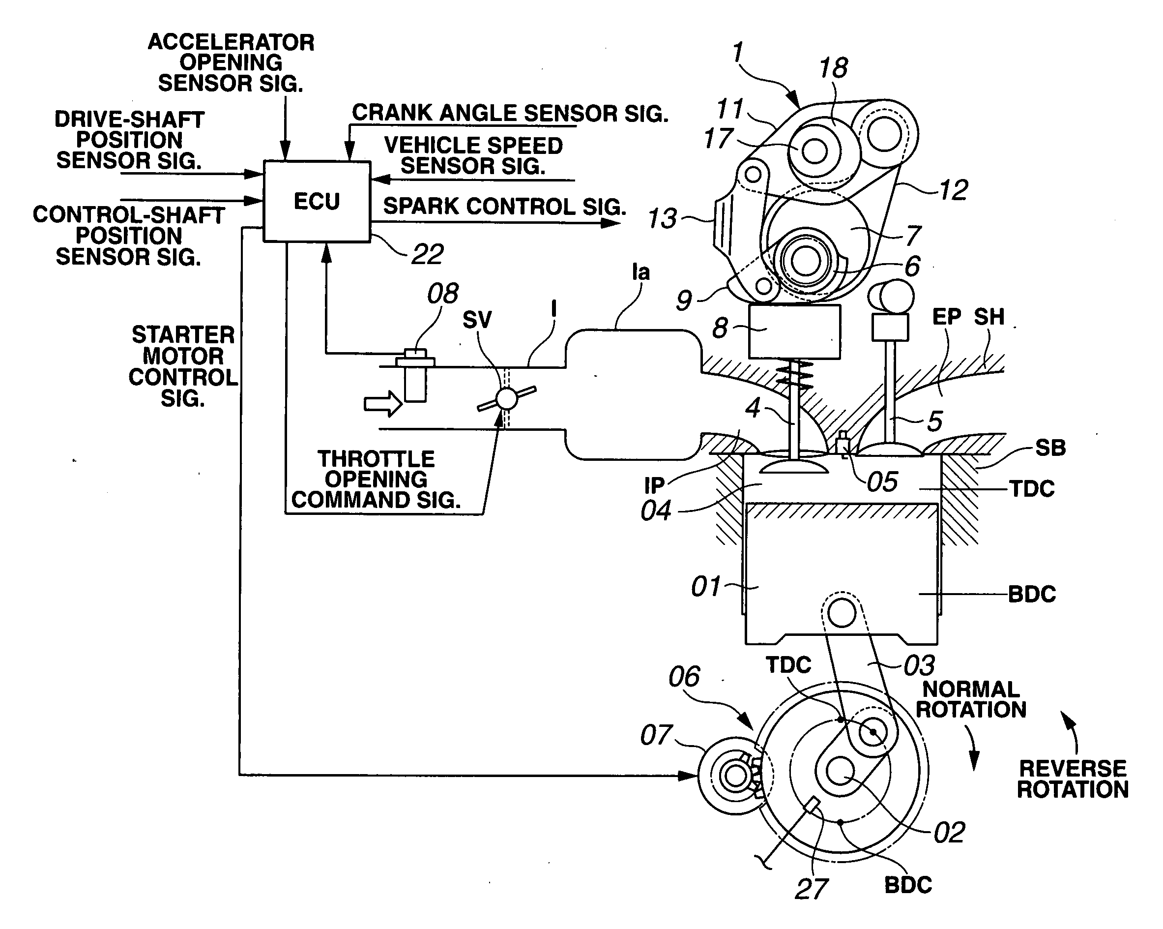
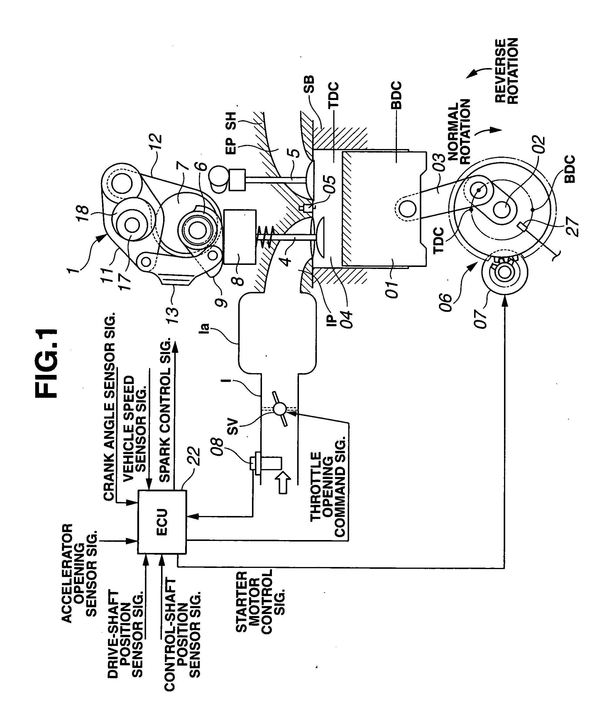
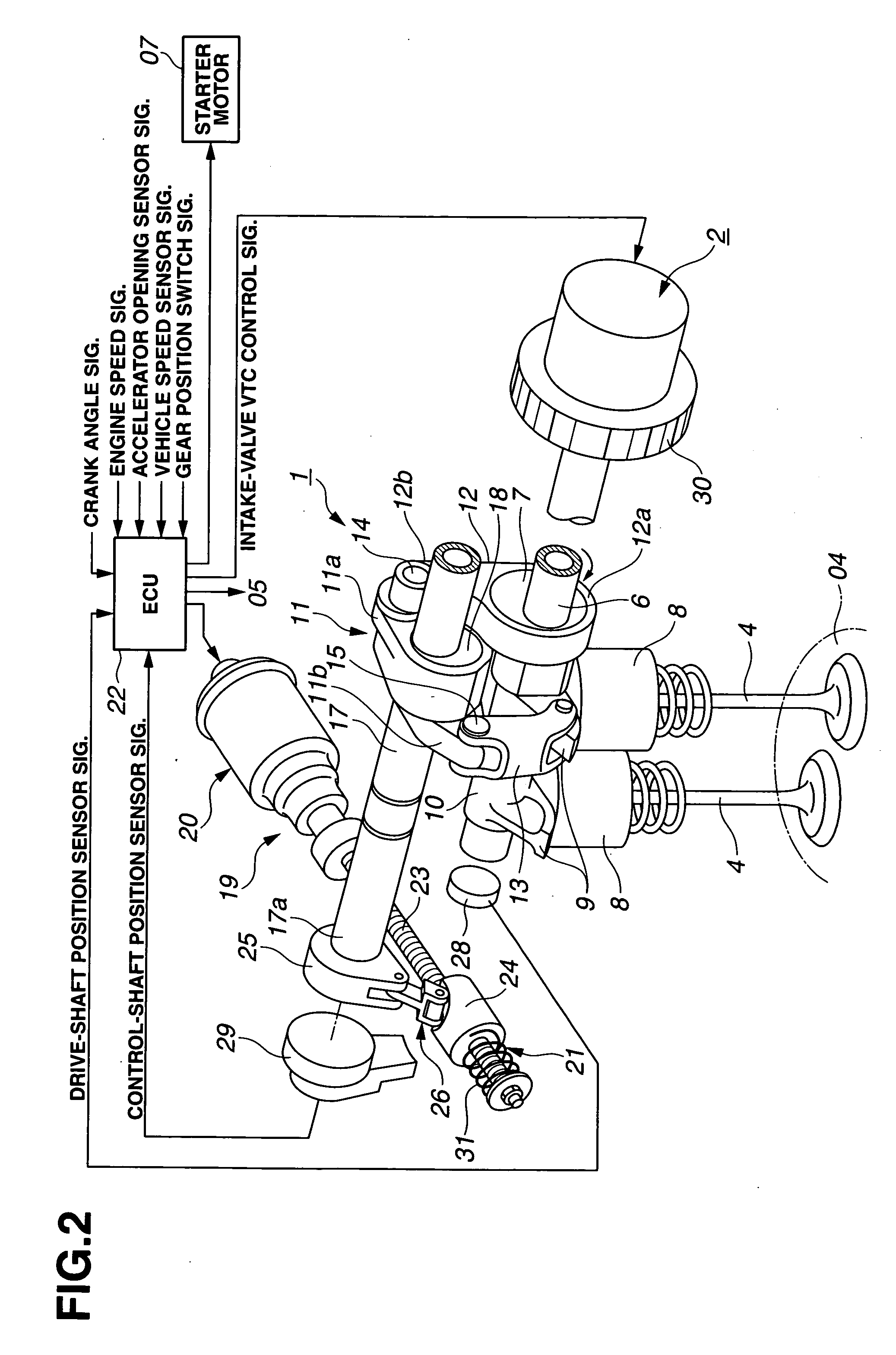
[0026]Referring now to the drawings, particularly to FIGS. 1-2, the variable valve actuation system of the embodiment is exemplified in a four-cycle multiple-cylinder internal combustion engine having four valves per cylinder, namely two intake valves 4, 4 (see FIGS. 1-2) and two exhaust valves 5, 5 (see FIG. 1).

[0027]The construction of the multiple-cylinder internal combustion engine, to which the variable valve actuation system of the embodiment can be applied, is hereunder described in detail in reference to the system diagram of FIG. 1. The engine of FIG. 1 is constructed by a cylinder block SB having a cylinder bore, a reciprocating piston 01 movable or slidable through a stroke in the cylinder bore, a cylinder head SH on the cylinder block SB, an intake port IP and an exhaust port EP formed in cylinder head SH, two intake valves 4, 4 each slidably installed on cylinder head SH for opening and closing the opening end of intake port IP, and two exhaust valves 5, 5 each slidably...


PUM


Abstract

In a variable valve actuation system of an internal combustion engine employing a variable valve actuator capable of variably adjusting at least intake valve closure timing depending on engine operating conditions, a processor of a control unit is programmed to phase-advance the intake valve closure timing to a predetermined timing value after a piston top dead center position and before a piston bottom dead center position on intake stroke during at least one of an engine starting period and an engine stopping period. The variable valve actuator includes a biasing device by which the intake valve closure timing is permanently biased toward the predetermined timing value.

Description

TECHNICAL FIELD[0001]The present invention relates to a variable valve actuation system of an internal combustion engine, and specifically to a system capable of suppressing or reducing noise and vibrations produced during an engine starting period such as during an early stage of cranking.BACKGROUND ART[0002]In recent years, there have been proposed and developed various variable valve actuation systems capable of variably adjusting an engine valve timing depending on operating conditions of an internal combustion engine. One such variable valve actuation system has been disclosed in Japanese Patent Provisional Publication No. 10-227236 (hereinafter is referred to as “JP10-227236”). The variable valve actuation system disclosed in JP10-227236 is comprised of a so-called rotary vane type valve timing control (VTC) system. In such a rotary vane type VTC system, working fluid pressure is supplied selectively into either one of phase-advance and phase-retard chambers defined in a rotar...

Claims


Application Information

Patent Timeline
IPC IPC(8): F01L1/34
CPCF01L1/3442F01L13/0026F01L2001/0475F01L2001/34469F01L2001/34483F01L2013/0073F01L2800/03F01L2001/34479
Inventor NAKAMURA, MAKOTOHARA, SEINOSUKE
Owner HITACHI LTD
Why Eureka
Try Eureka