Heat exchanger

Inactive Publication Date: 2007-06-28
KEIHIN THERMAL TECH CORP
View PDF9 Cites 23 Cited by
  • Summary
  • Abstract
  • Description
  • Claims
  • Application Information

AI Technical Summary

Benefits of technology

[0044] In fabricating a heat exchanger using the header tank described in par. 12), the contour of the header tank indicates the proper longitudinal orientation of the header tank, reliably obviating the likelihood that the header tank will be assembled into the exchanger, as oriented in the opposite direction. Accordingly, when the header tank is provided inside thereof with means for improving the performance of the heat exchanger, the means can be positioned accurately as determined, consequently giving improved heat exchange performance to the exchanger having the header tank incorporated therein. When the header tank, as held by a jig having a recessed portion for an outer portion of the tank to fit in, is to be assembled into a heat exchanger, the header tank, if oriented in the opposite direction, will not fit into the recessed portion of the jig. This automatically indicates whether the header tank is oriented in the opposite direction.
[0045] In the case of the heat exchanger header tanks described in par. 13) and 14), the front and rear portions of the header tank can be made asymmetric in cross sectional contour relatively easily.
[0046] In fabricating the heat exchangers described in par. 15) and 18), the contour of the header tank indicates the proper longitudinal orientation of the header tank, reliably obviating the likelihood that the header tank will be assembl

Problems solved by technology

However, the front and rear portions of the first header tank are symmetric in cross sectional contour, and the flow dividing resistance plate can not be recognized from outside, so that in assembling the components for the fabrication of the evaporator, it is likely that the header tank will be incorporated into the assembly, as oriented longitudinally in the opposite direction.
It is then almost impossible to obtain the effect to cause the refrigerant to flow through all the heat exchange tubes in uniform quantities, and there is the likelihood of the evaporat

Method used


Image

  • Heat exchanger
  • Heat exchanger
  • Heat exchanger

Examples


first embodiment

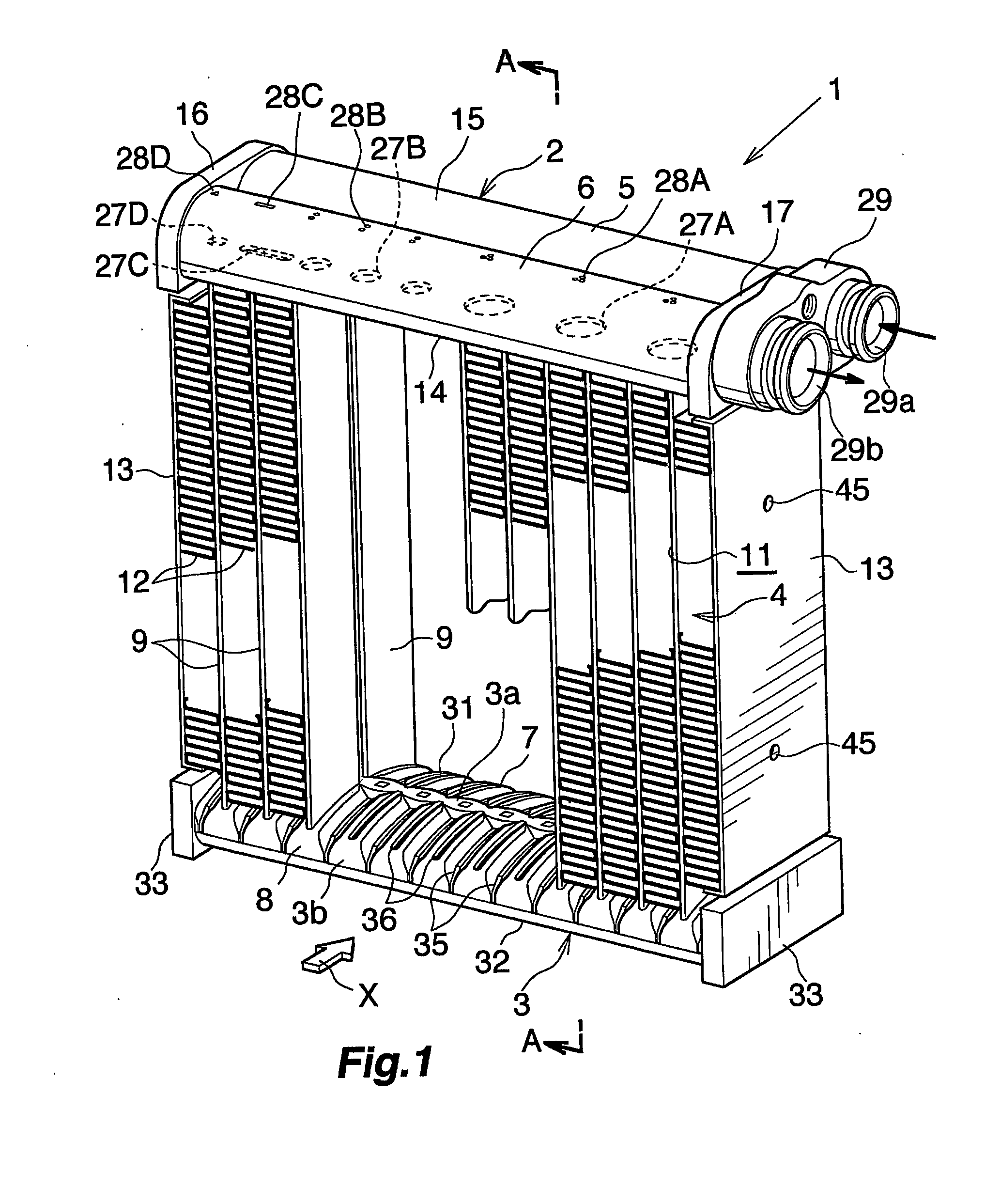
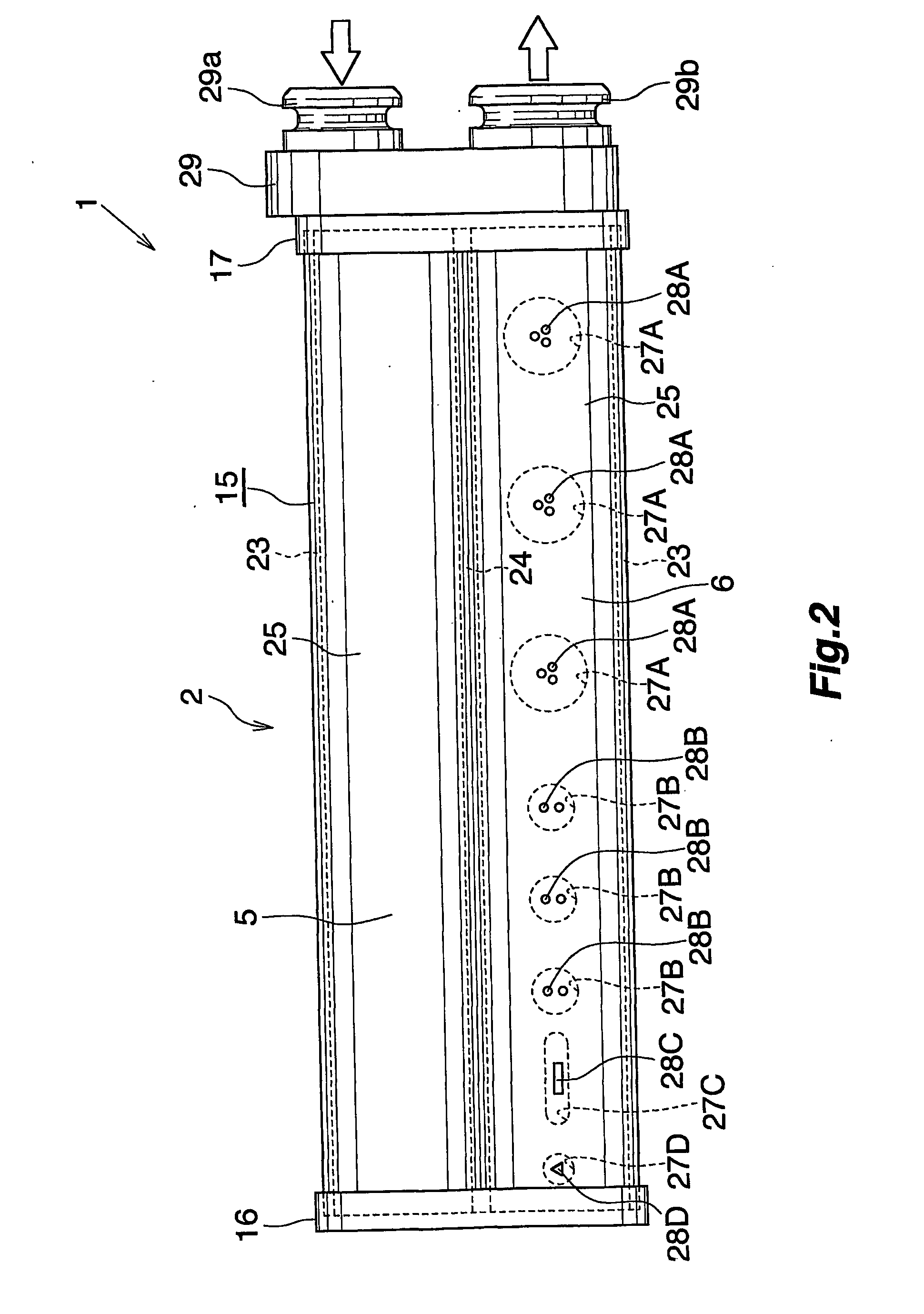
[0054] FIGS. 1 to 3 show the overall construction of evaporator according to the invention, and FIGS. 4 to 7 show the constructions of main parts. FIG. 8 shows a method of assembling heat exchange tubes, fins and side plates in fabricating the evaporator, and FIG. 9 shows the flow of a refrigerant through the evaporator.

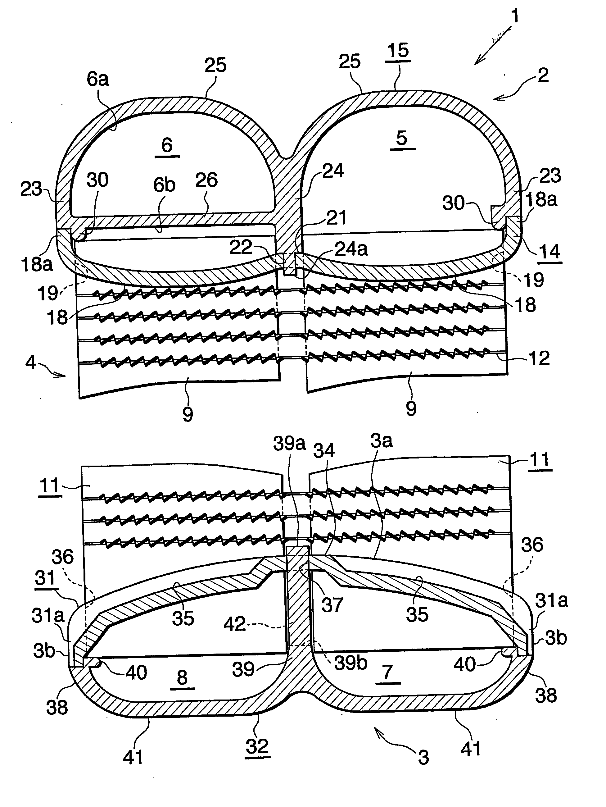
[0055]FIG. 1 shows an evaporator 1 which comprises a refrigerant inlet-outlet header tank 2 of aluminum and a refrigerant turn header tank 3 of aluminum which are arranged as vertically spaced apart, and a heat exchange core 4 provided between the two header tanks 2, 3.

[0056] The refrigerant inlet-outlet header tank 2 comprises a refrigerant inlet header 5 positioned on the front side (downstream side with respect to the flow of air through the evaporator) and a refrigerant outlet header 6 positioned on the rear side (upstream side with respect to the flow of air). The refrigerant turn header tank 3 comprises a refrigerant inflow header 7 as an intermediate header p...

second embodiment

[0092] FIGS. 10 to 13 show evaporator according to the invention.

[0093]FIGS. 10 and 11 show the overall construction of the evaporator, and FIGS. 12 and 13 show the constructions of main portions.

[0094] In the case of the embodiment shown in FIGS. 10 to 13, the flow dividing resistance plate 26 of the second member 15 of the refrigerant inlet-outlet header tank 2 has a plurality of laterally elongated refrigerant passing holes 51A, 51B arranged at a spacing in the lateral direction and formed in the rear portion of the plate 26 except the left and right end portions thereof, instead of the refrigerant passing holes 27A, 27B, 27C, 27D which are different in shape and / or size. The hole 51A in the center is shorter than the other holes 51B.

[0095] One of the two generally circular-arc connecting walls 25 of the second member 15, i.e., the rear connecting wall 25, is integrally provided on the outer surface thereof with a ridge 52 extending longitudinally of the wall and positioned awa...


PUM


Abstract

A heat exchanger includes a heat exchange core including a plurality of heat exchange tubes, a refrigerant inlet header and a refrigerant outlet header arranged toward one end of each heat exchange tube, and a refrigerant inflow header and a refrigerant outflow header arranged toward the other end of each heat exchange tube. The outlet header has an interior divided into two spaces by a flow dividing resistance plate, and some of the heat exchange tubes are joined to the outlet header so as to communicate with the space. The resistance plate has a plurality of refrigerant passing holes formed therein that are different in shape and/or size. The outlet header is provided on the outer surface thereof with identification marks for discriminating the positions of the refrigerant passing holes and representing the shapes and/or sizes of the holes.

Description

CROSS REFERENCE TO RELATED APPLICATIONS [0001] This application is an application filed under 35 U.S.C. §111(a) claiming the benefit pursuant to 35 U.S.C. §119(e)(1) of the filing date of Provisional Applications No. 60 / 497,338 and No. 60 / 555,706 filed Aug. 25, 2003 and Mar. 24, 2004, respectively, pursuant to 35 U.S.C. §111(b).TECHNICAL FIELD [0002] The present invention relates to heat exchangers, and more particularly to heat exchangers for use as evaporators in motor vehicle air conditioners which are refrigeration cycles to be installed in motor vehicles. [0003] The downstream side (the direction indicated by the arrow X in FIGS. 1 and 10, and the right-hand side of FIGS. 3 and 11) of the air to be passed through the air flow clearance between each adjacent pair of heat exchange tubes will be referred to herein and in the appended claims as “front,” and the opposite side as “rear.”BACKGROUND ART [0004] Heretofore in wide use as motor vehicle evaporators are those of the so-call...

Claims


Application Information

Patent Timeline
IPC IPC(8): F28F9/02F28D1/053F28F27/02
CPCF28D1/05375F28D1/05391F28D2021/0085F28F9/0204F28F9/0278F28F2255/16F28F2280/04F25B39/00F28D1/04F28D1/053F28F9/22
Inventor WATANABE, HIROHIKOARINO, KOUTA
Owner KEIHIN THERMAL TECH CORP
Why Eureka
Try Eureka