Clutch mechanism free from influence of axial displacement of rotary member

a technology of rotary member and clutch mechanism, which is applied in the direction of clutches, non-mechanical actuator clutches, gear lubrication/cooling, etc., can solve the problems of generating axial thrust force as reaction force components, vibration and noise, and helical gears smeared, etc., to achieve the effect of effectively suppressing mutual interference, eliminating or reducing undesirable vibrational fluctuation of driving torque, and effectively suppressing torque transmission through the clutch

Inactive Publication Date: 2007-06-28
HITACHI LTD
View PDF4 Cites 14 Cited by
  • Summary
  • Abstract
  • Description
  • Claims
  • Application Information

AI Technical Summary

Benefits of technology

[0011] The described arrangement effectively suppresses mutual interference between the clutch actuating force which presses the first and second friction discs of the clutch pack and the axial thrust component generated by the helical gears which serve as the torque input and output rotary components of a transmission, thereby eliminating or reducing undesirable vibratory fluctuation of the driving torque transmitted through the clutch.
[0012] The present invention effectively suppresses variation of the torque transmitted through the clutch attributable to axial displacement of parts or components such as an input shaft and an output gear caused by thrust forces generated by meshing helical gears incorporated in the transmission. Thus, the present invention provides a transmission with reduced torque fluctuation, which in turn contributes to improvement in drivability and comfort of automobiles.

Problems solved by technology

Meshing helical gears, however, undesirably generate axial thrust force as reaction force components, due to slanting of the gear teeth.
Such axial thrust force is not only wasteful but also cause vibration and noise, while involving a risk of producing undesirable effects on other components of the transmission.
Such vibration, noise and undesirable effect on other components disadvantageously depreciate commercial values of the transmissions and, hence, of automobiles mounting such transmissions.
The thrust force deconcentrating arrangement disclosed in the above-mentioned publication, although effective in reducing mechanical stress in the bearing as a result of distribution of the axial thrust force, cannot completely eliminate axial displacement of the gear: namely, the gear tends to be axially displaced although the amount of the displacement is very small.
Therefore, problems such as vibration, noise, and undesirable effects on transmission components still remain unsolved.
The problems are serious particularly in power transmission system in which a clutch mechanism is disposed adjacent to the gears under thrust force, since in most cases operation of clutches relies upon axial forces which act in the same directions as the axial force components generated on the gears.
More specifically, even a small axial displacement of the gear causes a variation in the axial force which actuates the clutch, with the result that the torque transmitted through the clutch fluctuates to impair the drivability or comfort of the automobile.

Method used


Image

  • Clutch mechanism free from influence of axial displacement of rotary member
  • Clutch mechanism free from influence of axial displacement of rotary member
  • Clutch mechanism free from influence of axial displacement of rotary member

Examples


Embodiment Construction

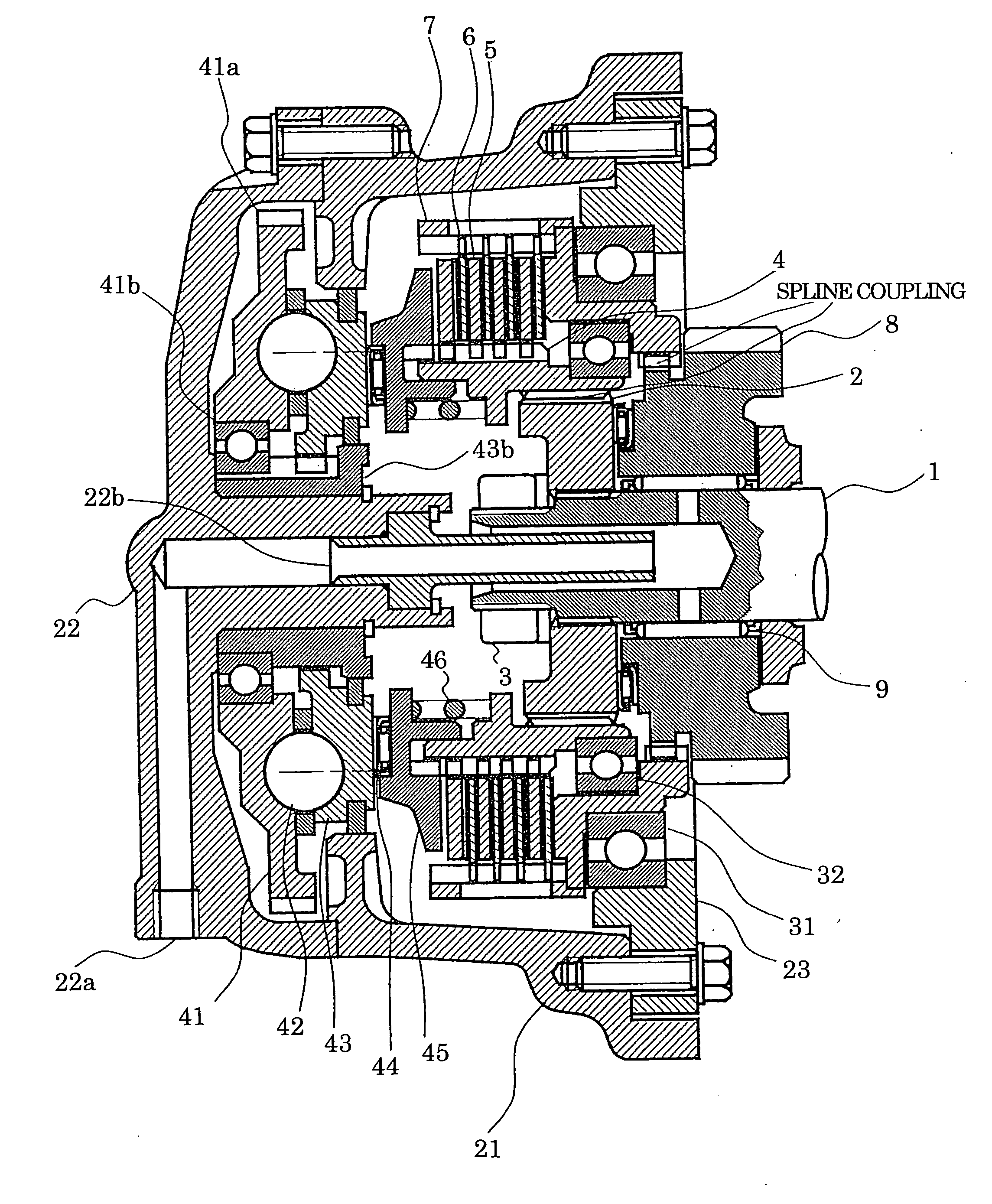
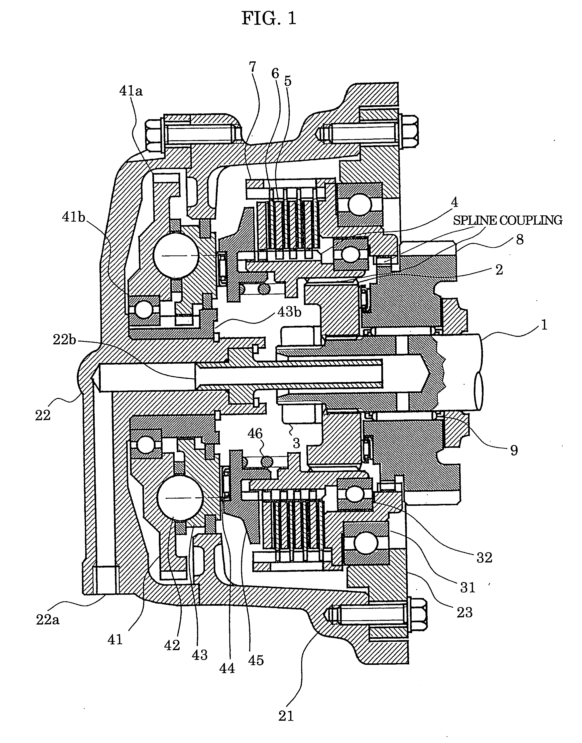
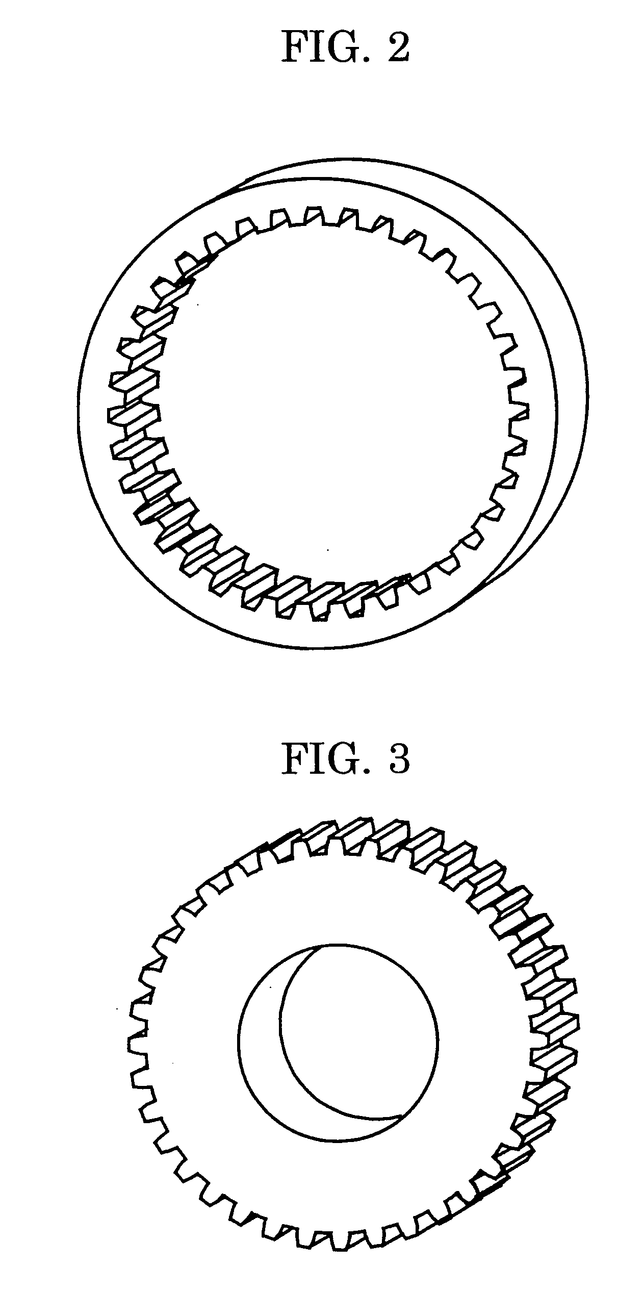
[0021] An embodiment of the present invention will be described with reference to FIGS. 1 to 5. Referring to these Figures, a clutch mechanism embodying the present invention has the following parts or components: an input shaft 1 carrying an inner hub 2 fastened thereto by a shaft end nut 3; a hub 4; first friction discs 5; second friction discs 6; a drum 7; a gear 8 supported by needle bearings 9; a clutch case 21; an end cap 22 having a lubrication oil port 22a; a lubrication oil supply pipe 22b; an intermediate plate 23; a drum support bearing 31; a hub supporting bearing 32; a rotary ramp member 41; a gear 41a; a rotary ramp support bearing 41b; balls 42; a translational ramp member 43; a guide member 43b; a thrust bearing 44; and a pressure plate 45. In FIGS. 5A and 5B illustrating the principle of operation of the ball-ramp type clutch actuator, numerals 52, 53 denote discs, while numeral 53 denotes balls.

[0022] Referring specifically to FIG. 1, the input shaft 1 serving as ...


PUM


Abstract

A clutch mechanism includes: an input rotary member for receiving an input torque; a hub for receiving the torque from the input rotary member; first friction discs held by the hub; second friction discs arranged to be pressed against the first friction discs to achieve a torque-transmitting engagement therebetween; a drum supporting the second friction discs and stopped by the drum support bearing against movement in one axial direction; and an output rotary member for receiving the torque from the drum. Transmission of the torque from the drum to the output rotary member is achieved by a spline coupling therebetween. Axial movement of the drum in one direction is stopped by an end surface of a drum support bearing mounted in a housing. The hub is splined to the input rotary member for axial movement relative to the rotary input member.

Description

BACKGROUND OF THE INVENTION [0001] 1. Field of the Invention [0002] The present invention relates to an automotive clutch mechanism and, more particularly, to a clutch mechanism improved to avoid undesirable effect caused by variations of axial positions of input and output shafts of the clutch mechanism. [0003] 2. Description of the Related Art [0004] In general, an automotive transmission employs speed-reducing gear trains composed of a plenty of gears. In order to achieve high quietness while assuring high endurance, helical gears having gear teeth slanting with respect to the gear axes are used as the transmission gears. Meshing helical gears, however, undesirably generate axial thrust force as reaction force components, due to slanting of the gear teeth. [0005] Such axial thrust force is not only wasteful but also cause vibration and noise, while involving a risk of producing undesirable effects on other components of the transmission. Such vibration, noise and undesirable effe...

Claims


Application Information

Patent Timeline
Patent Type & Authority Applications(United States)
IPC IPC(8): F16D13/42F16D13/52F16D13/60
CPCF16D13/54F16D27/004F16D28/00F16H57/04F16D13/52F16D2023/123
Inventor YAMASAKI, MASARUMORITA, MINORUKONNO, HITOSHIKUROIWA, HIROSHIYOSHIDA, YOSHIYUKISHISHIDO, KENTARO
Owner HITACHI LTD
Why Eureka
Try Eureka