Jetting dispenser with multiple jetting nozzle outlets

a dispenser and outlet technology, applied in the direction of spray nozzles, movable measuring chambers, coatings, etc., can solve the problem of limited throughput of conventional jetting dispensers, and achieve the effect of increasing throughput and reducing cycle times

Inactive Publication Date: 2007-06-28
NORDSON CORP
View PDF80 Cites 56 Cited by
  • Summary
  • Abstract
  • Description
  • Claims
  • Application Information

AI Technical Summary

Benefits of technology

[0006] The present invention provides a liquid dispensing system, or jetting dispenser, capable of simultaneously jetting multiple droplets of liquid material. The droplets may be dispensed to a substrate such that the droplets remain separate from one another, or it may be desired that the droplets merge or coalesce to form a bead or layer of liquid material. A jetting dispenser in accordance with the principles of the present invention therefore may achieve reduced cycle times and a multi-fold increase in throughput, compared to conventional jetting dispensers, and / or other desirable results.

Problems solved by technology

The throughput of conventional jetting dispensers is limited by the mechanical speed of the actuating mechanisms which create the droplets of liquid material that are jetted to a substrate.

Method used


Image

  • Jetting dispenser with multiple jetting nozzle outlets
  • Jetting dispenser with multiple jetting nozzle outlets
  • Jetting dispenser with multiple jetting nozzle outlets

Examples


Embodiment Construction

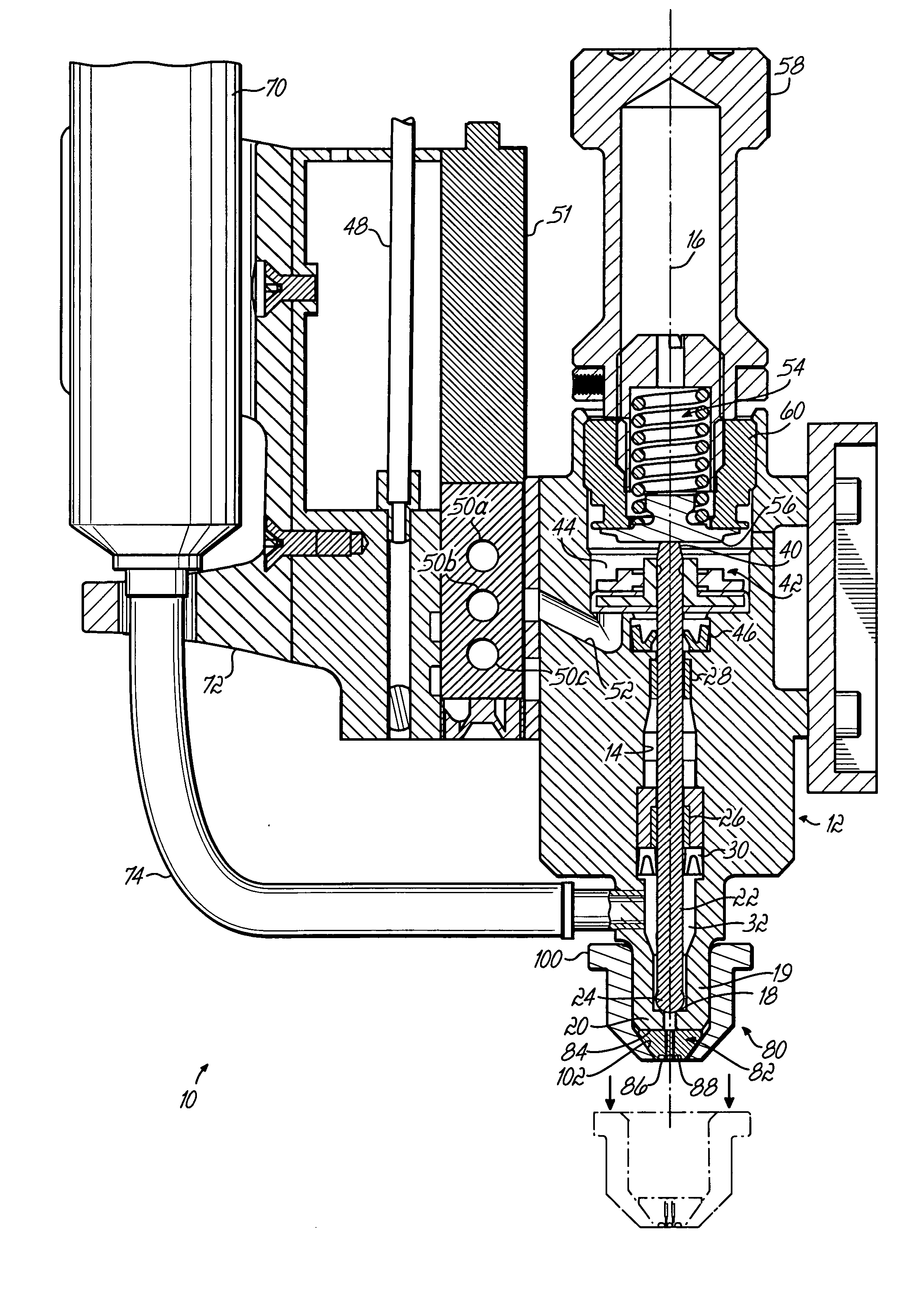
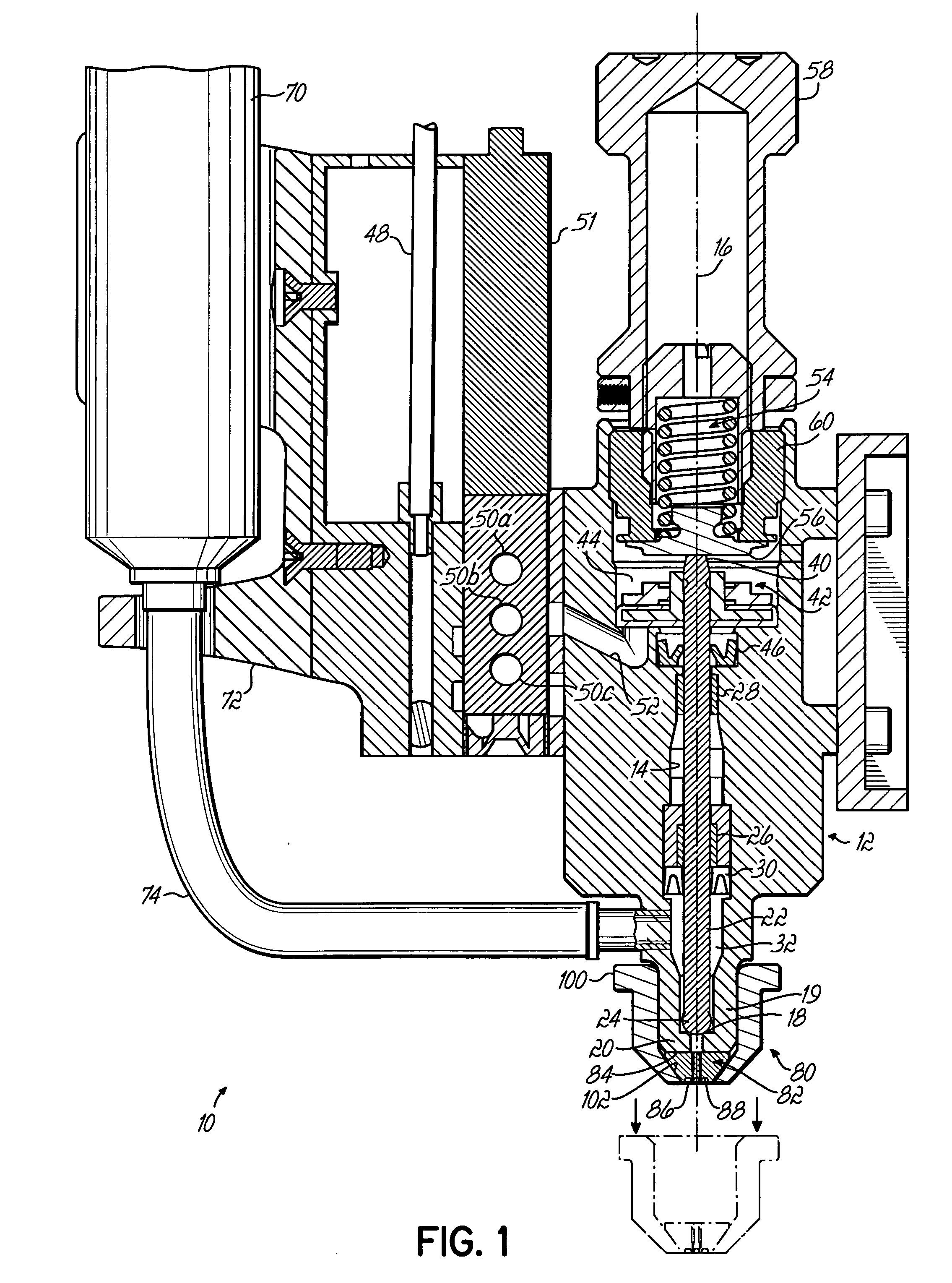
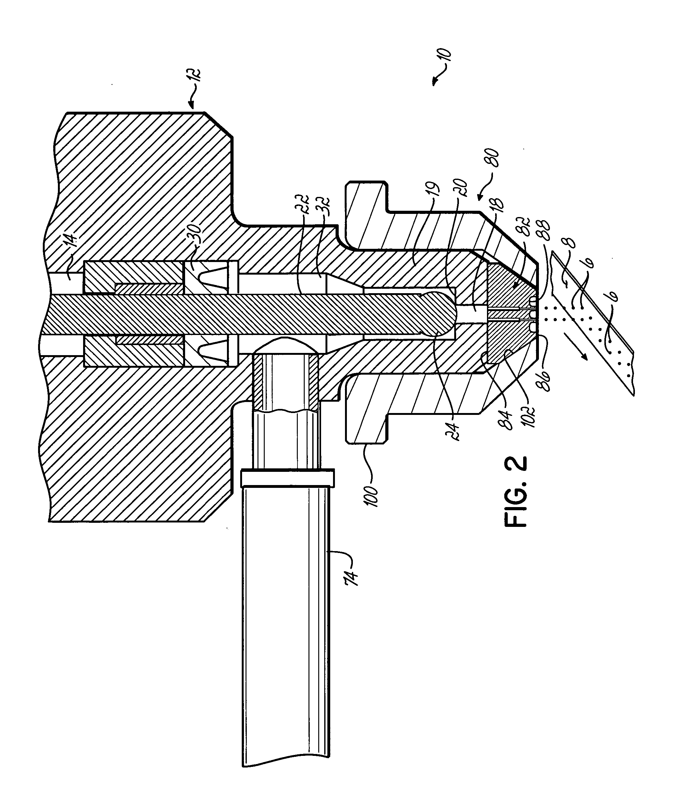
[0020]FIGS. 1 and 2 depict an exemplary liquid dispensing system 10 in accordance with the principles of the present invention and configured to jet droplets 6 of liquid material to a substrate 8. In the embodiment shown, substrate 8 is moved in the direction of the arrow to control the placement of droplets 6 on the substrate. It will be appreciated, however, that the dispensing system 10 may alternatively be moved relative to the substrate 8. Such liquid dispensing systems are commonly referred to as “jetting dispensers”. One example of a jetting dispenser that may be used to carry out the invention is shown and described in co-pending PCT Application US2004 / 020247 (Publication No. WO 2005 / 009627) filed Jun. 25, 2004, although it will be recognized that various other types of jetting dispensers could be used as well, and the principles of the present invention are not limited to use with the particular jetting dispenser disclosed therein. PCT Application US / 2004 / 020247 is commonly...


PUM


Abstract

A jetting dispenser has a dispenser body with a fluid channel and a fluid channel outlet within the fluid channel. A valve member is movable within the fluid channel for selective contact with a valve seat near the fluid channel outlet. A jetting nozzle is adapted to be coupled to the dispenser body, adjacent the channel outlet, and has a nozzle body with a plurality of nozzle outlets in fluid communication with the channel outlet via a plurality of fluid passages through the nozzle body. The valve member is moved by a valve driver to contact the valve seat and impart momentum to liquid material supplied to the dispenser such that a plurality of droplets of liquid material are simultaneously jetted from the plurality of nozzle outlets.

Description

FIELD OF THE INVENTION [0001] The present invention generally relates to liquid material dispensing apparatus, and more particularly to a non-contact jetting dispenser for dispensing discrete amounts of liquid material to a substrate. BACKGROUND OF THE INVENTION [0002] Liquid dispensing systems have become an integral part of the electronics manufacturing process for depositing underfill, encapsulants, solder fluxes, surface mount adhesives, conformal coatings, and other materials onto a substrate, such as a printed circuit board. Each liquid dispensing system used in the electronics manufacturing process has a particular dispensing characteristic that is determined in large measure by the desired liquid dispense pattern on the substrate, the liquid flow rate and / or liquid viscosity of the dispensed material, and the desired electronic component assembly throughput through the dispensing system. [0003] For example, in the assembly of ball grid arrays (BGAs) and other electronic comp...

Claims


Application Information

Patent Timeline
Patent Type & Authority Applications(United States)
IPC IPC(8): B05B1/30
CPCB05C5/0225B05C5/0275B05C11/1034G01F11/12G01F11/22
Inventor AHMADI, MANIBABIARZ, ALECCIARDELLA, ROBERTFANG, LIANGFISKE, ERIKQUINONES, HORATIORATLEDGE, THOMAS L.
Owner NORDSON CORP
Why Eureka
Try Eureka