Electronic commutator circuits

a commutator circuit and electronic technology, applied in the direction of multiple motor speed/torque control, dynamo-electric machines, synchronous motor starters, etc., can solve the problems of low duty cycle conduction conditions, high on-state voltage drop, and lack of internal regenerative properties of structures, so as to reduce power losses and component stresses

Inactive Publication Date: 2007-06-28
GE POWER CONVERSION
View PDF25 Cites 3 Cited by
  • Summary
  • Abstract
  • Description
  • Claims
  • Application Information

AI Technical Summary

Benefits of technology

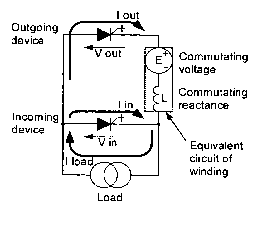
[0020] The use of such first and second semiconductor power devices in place of conventional thyristors means that the electronic commutator circuit can force the commutation of current irrespective of the voltage in the stator winding.
[0022] A preferred type of semiconductor power device is the Reverse Blocking Gate Turn Off Thyristor (RB-GTO). RB-GTOs and RB-GTO derivatives benefit from reduced on-state losses relative to other gate commutated device families such as IGBTs as a result of their internal regenerative properties. The switch stage currents take the form of low duty cycle pulsed waveforms with a high peak / mean ratio. Furthermore, the required switching frequency is relatively low (at least by current standards) being equal to the fundamental frequency of the stator and typically less than 100 Hz. RB-GTOs and RB-GTO derivatives with compression mounted hermetically sealed packages are well suited for use with the electronic commutator circuits of the present invention because they provide a near ideal compromise between on-state and switching losses, while at the same time being very reliable.
[0026] The reactor preferably includes a core that saturates at a small fraction of the rated machine winding current of the dc electrical machine. The core saturation will preferably occur at a reactor winding current of less than 10% of the rated machine winding current. The saturated value of the reactor winding inductance is also preferably less than 1% of the inductance of the stator winding measured between two adjacent points of common coupling and is most preferably as small as is practically achievable. The ratio of the un-saturated value of the reactor winding inductance divided by the saturated value of the reactor winding inductance is preferably greater than a factor of 10 and is most preferably as large as is practically achievable. The objective of the saturable reactor is to reduce the rate of change of the current in the associated first and second semiconductor power devices and hence reduce switching power losses. The reduction in the rate of change of the current is only needed at times of low current flow and at current reversals. The reactor is therefore preferably non-obtrusive at all other times during the operation of the electronic commutator circuit. Hence the desire to employ the largest practical ratio of un-saturated to saturated inductance and the lowest possible saturation current.
[0041] The phase controller may regulate the load angle to be substantially zero so that the stepwise rotation of the stator MMF (and the gate commutations) occur at points in the stator voltage waveforms where the corresponding incoming and outgoing semiconductor power device waveforms are at or near minimum amplitude in order to reduce power losses and component stresses associated with the commutation process. In other words, the load angle can be regulated to adjust the axis of stator current injection, with respect to the axis of stator voltage, so as to cause the gate commutations to occur at points in the stator voltage waveforms where the corresponding incoming and outgoing semiconductor power device waveforms are at or near minimum amplitude.

Problems solved by technology

However, these structures do not have internal regenerative properties and their relatively high on-state voltage drops are not ideally suited to the low duty cycle conduction conditions that apply to this type of electronic commutator circuits.

Method used


Image

  • Electronic commutator circuits
  • Electronic commutator circuits
  • Electronic commutator circuits

Examples


Embodiment Construction

[0066]FIGS. 6A and 6B show a gate commutated forced commutation of a Reverse Blocking Gate Turn Off Thyristor (RB-GTO) in a simplified form. In FIG. 6A, a RB-GTO employs a series connected resistor-capacitor switching aid network (snubber) that is connected in parallel with the power terminals of the RB-GTO. A gating system is employed and this is depicted as a current source “I gate”. The load is depicted as a current source “I load”. Associated current and voltage waveforms are shown with respect to time in FIG. 6B.

[0067] Prior to commutation, load current “I load” flows through the power terminals of the RB-GTO. The current flowing through the RB-GTO, represented by “I cathode” is therefore equal to the load current “I load” while the current source “I gate” and the current flowing through the snubber “I snubber” are both zero. The RB-GTO is considered to be latched in the on state.

[0068] To initiate the commutation, the current source “I gate” is injected with the appropriate ...


PUM


Abstract

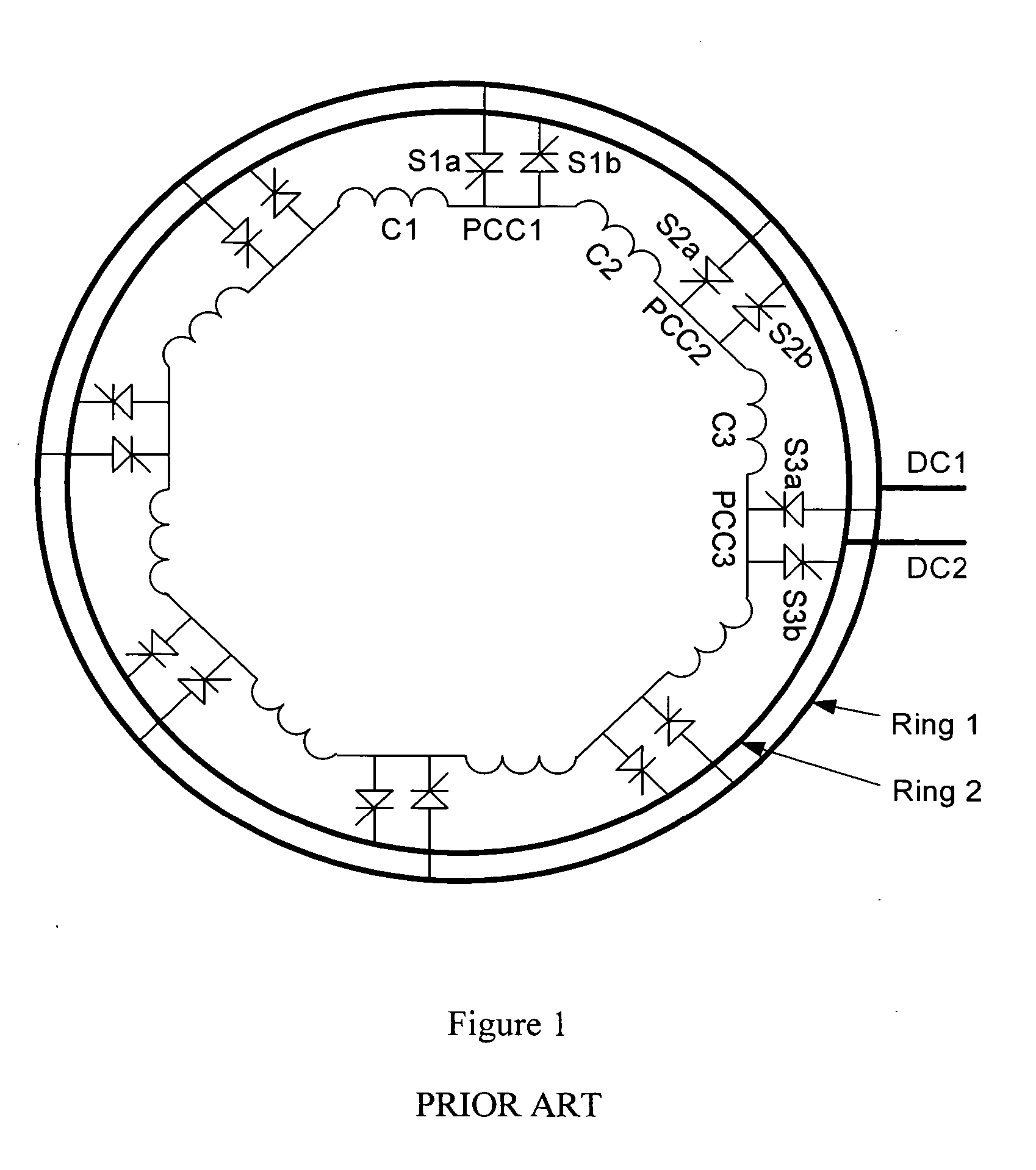
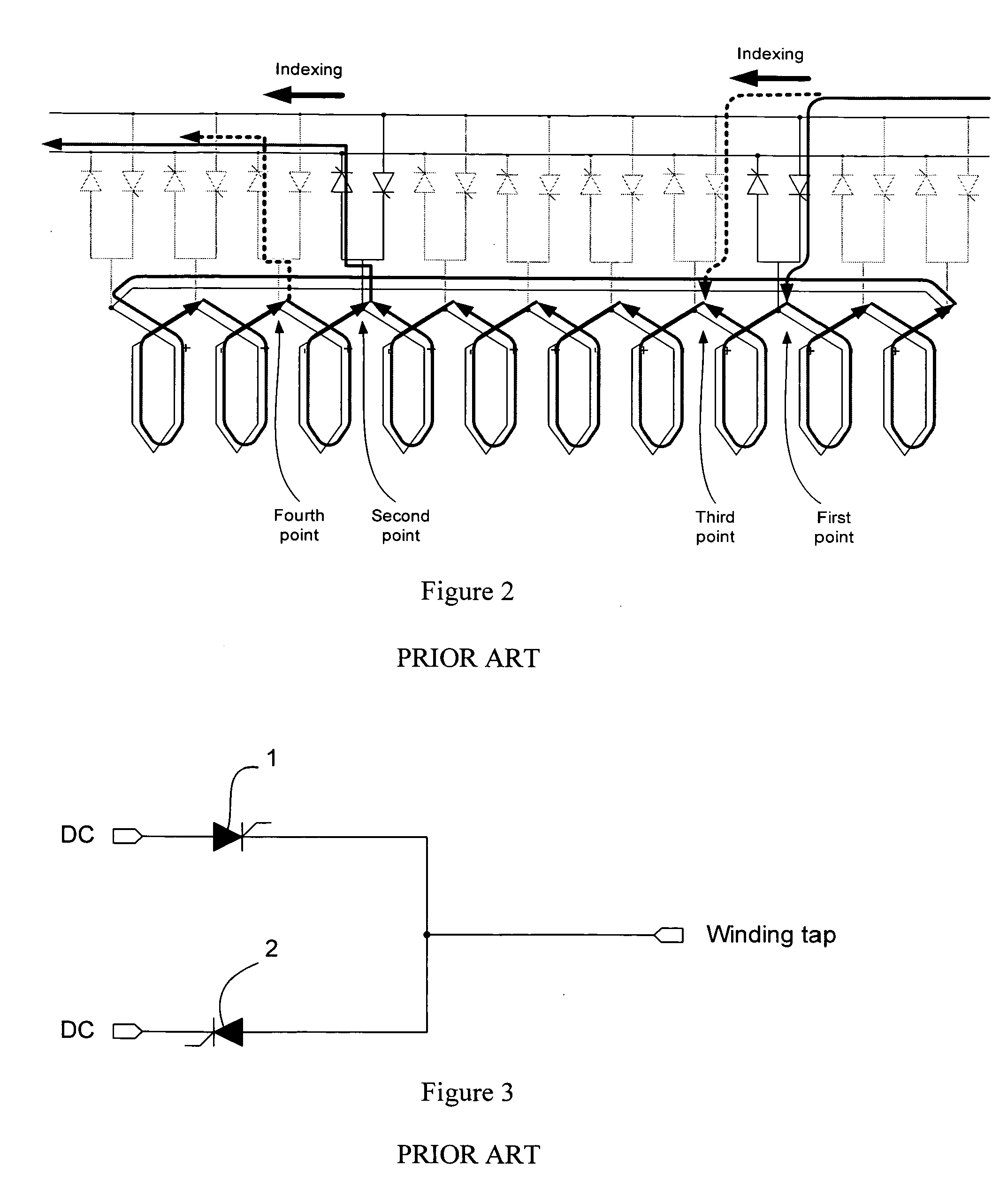
The present invention provides an electronic commutator circuit for use with a stator winding of an electrical machine. The stator winding of the electrical machine includes a number of coils linked by the same number of points of common coupling. The electronic commutator circuit comprising the same number of switching stages, each switching stage being connected between a respective one of the points of common coupling and first and second dc terminals. Each switching stage further includes a first reverse blocking semiconductor power device (such as a Reverse Blocking Gate Turn Off Thyristor (RB-GTO 1) capable of being turned on and off by gate control having its anode connected to the first dc terminal, and a second reverse blocking semiconductor power device (RB-GTO 2) capable of being turned on and off by gate control having its cathode connected to the second dc terminal.

Description

FIELD OF THE INVENTION [0001] The present invention relates to electronic commutator circuits, and in particular to circuits for rotating and linear machines (such as brushless dc rotating and linear machines, for example) that employ forced electronic commutation. BACKGROUND OF THE INVENTION [0002] A dc rotating machine typically includes a rotor surrounded by a wound stator. A rotor connected commutator with copper segments and stationary brushgear are used to control the commutation of current in the rotor winding based on the angular position of the rotor. In a further development of the dc rotating machine, an electronic switching circuit is used to control the commutation of current in the stator winding based on the angular position of the rotor. The rotor provides a rotating magnetic field and this can be generated by permanent magnets, conventional windings with a slip ring or brushless excitation power supply, or superconducting windings with a suitable excitation power su...

Claims


Application Information

Patent Timeline
Patent Type & Authority Applications(United States)
IPC IPC(8): H02P25/12
CPCH02P8/00H03K2217/0036H03K17/06H02P25/021H02P25/024H02K29/00H02P6/14H02M1/08H02M1/16
Inventor CRANE, ALLAN DAVID
Owner GE POWER CONVERSION
Why Eureka
Try Eureka