Liquid-jet apparatus

a liquid-jet and apparatus technology, applied in the direction of printing, other printing apparatus, etc., can solve the problem of difficulty in realizing a high-speed recording operation

Inactive Publication Date: 2007-06-28
SEIKO EPSON CORP
View PDF2 Cites 8 Cited by
  • Summary
  • Abstract
  • Description
  • Claims
  • Application Information

AI Technical Summary

Benefits of technology

[0011] An advantage of some aspects of the invention is that it provides a liquid-jet apparatus, such as an ink-jet recording apparatus, capable of starting the next printing period while controlling the ejecting speed and amount of ink droplets ejected even when a meniscus is formed at the outside of a nozzle opening having ejected an ink droplet in the previous printing period, thereby achieving a high-speed recording operation.

Problems solved by technology

However, the method makes it difficult to realize a high-speed recording operation.

Method used


Image

  • Liquid-jet apparatus
  • Liquid-jet apparatus
  • Liquid-jet apparatus

Examples


Embodiment Construction

[0041] Hereinafter, preferred embodiments of the invention will be described below with reference to the accompanying drawings.

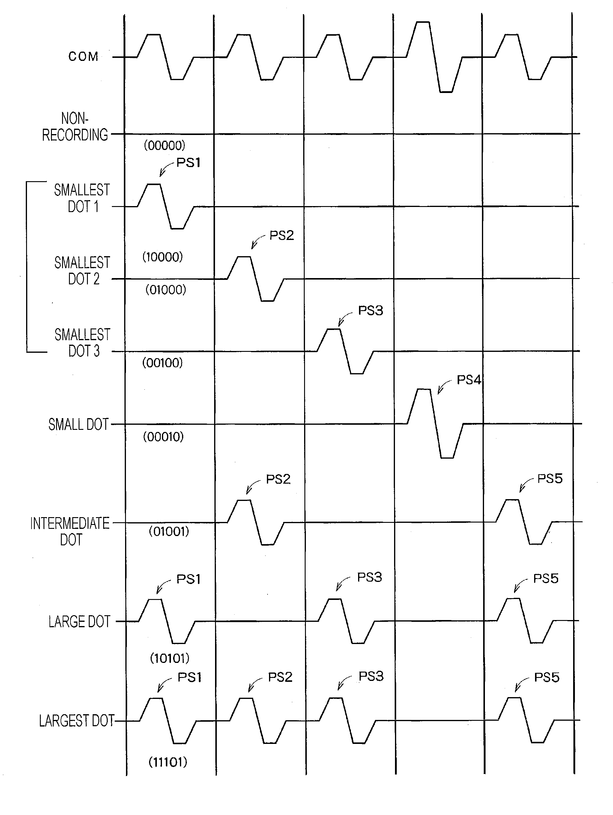
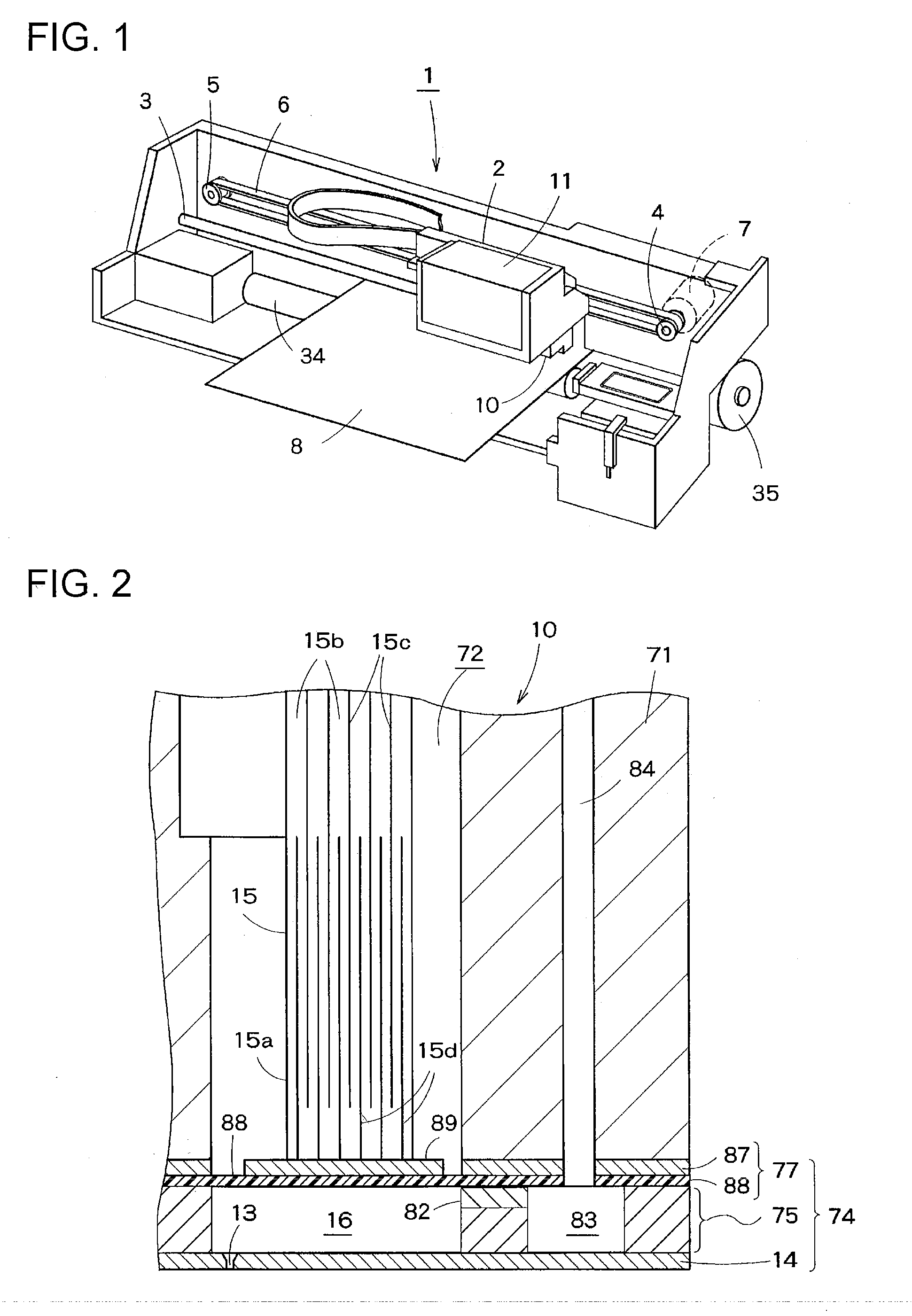
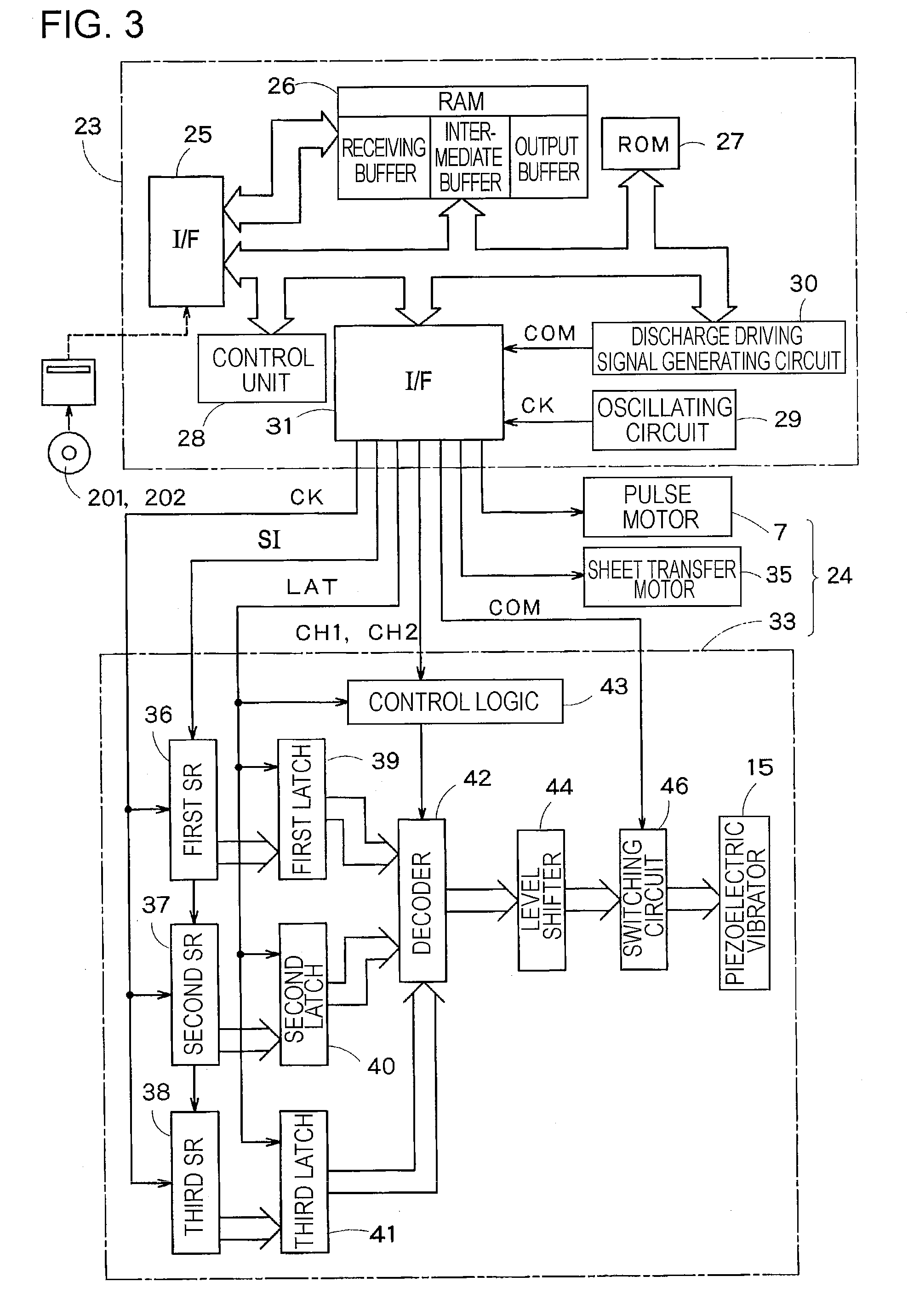
[0042]FIG. 1 is a perspective view schematically illustrating an ink-jet printer 1, which is a liquid-jet apparatus according to an embodiment of the invention. In the ink-jet printer 1, a carriage 2 is movably mounted to a guide member 3. The carriage 2 is connected to a timing belt 6 that is wounded around a driving pulley 4 and a free pulley 5. The driving pulley 4 is coupled to a rotational shaft of a pulse motor 7. In the above-mentioned structure, the driving of the pulse motor 7 causes the carriage 2 to move in the widthwise direction (scanning direction) of a recording sheet 8.

[0043] A recording head 10 (head member) is mounted on a surface (lower surface) of the carriage 2 opposite to the recording sheet 8.

[0044] As shown in FIG. 2, in the recording head 10, a comb-shaped piezoelectric vibrator 15 is inserted into a storage compartment 72 of a bo...


PUM


Abstract

A liquid-jet apparatus includes: a driving signal generating unit that generates a ejecting driving signal, which is a periodic signal having a plurality of pulse waveforms; a driving pulse generating unit that generates a driving pulse string for each unit region of a medium to be printed upon, on the basis of gray-scale data for the unit region, the ejecting driving signal, and information on whether the driving pulse string generated for a previous unit region includes a last pulse waveform or a pulse waveform immediately before the last pulse waveform in one cycle of the ejecting driving signal; and a control unit that drives the pressure changing unit on the basis of the driving pulse. In the liquid-jet apparatus, the one cycle of the ejecting driving signal corresponds to one unit region of the medium to be printed upon.

Description

The entire disclosure of Japanese Patent Application No. 2005-378664, filed Dec. 28, 2005 is expressly incorporated by reference herein. BACKGROUND [0001] 1. Technical Field [0002] The present invention relates to a liquid-jet apparatus for ejecting liquid droplets from nozzle openings, and more specifically, to a liquid-jet apparatus capable of ejecting liquid droplets from nozzle openings on the basis of driving pulses. [0003] 2. Related Art [0004] In ink-jet recording apparatuses (a kind of liquid-jet apparatus), such as ink-jet printers and ink-jet plotters, while a recording head (head member) is moved in the main scanning direction and a recording sheet (a kind of medium to be printed upon) is moved in the sub-scanning direction, ink droplets are discharged from nozzle openings of the recording head, thereby forming images (characters) on the recording sheet. For example, a pressure generating chamber communicating with the nozzle openings is compressed or decompressed to ejec...

Claims


Application Information

Patent Timeline
Patent Type & Authority Applications(United States)
IPC IPC(8): B41J29/38
CPCB41J2/04541B41J2/04543B41J2/04546B41J2/04581B41J2/04588
Inventor SAYAMA, TOMOHIRONAGATE, TORU
Owner SEIKO EPSON CORP
Why Eureka
Try Eureka