Planer lighting device and liquid crystal display device using the same

a technology of liquid crystal display and light guide plate, which is applied in the direction of display means, instruments, measurement apparatus components, etc., can solve the problems of limited light guide plate dimensions that can be prepared, joint to be perceived as either bright or dark lines, etc., and achieves a wide range of brightness, sufficient brightness, and increased area

Inactive Publication Date: 2007-06-28
FUJIFILM CORP
View PDF5 Cites 30 Cited by
  • Summary
  • Abstract
  • Description
  • Claims
  • Application Information

AI Technical Summary

Benefits of technology

[0029] The planar lighting devices according to the first and second aspects of the present invention have the advantage that even if a light guide plate comprising a plurality of light guide plate units connected together is used with a view to increasing the area from which illuminating light emerges, no perceivable bright or dark lines will be generated in the joint between adjacent light guide plate blocks so that a wide enough range can be illuminated with light in the absence of any unevenness in brightness.
[0030] The liquid crystal display device according to the third aspect of the present invention employs the planar lighting device according to the first or second aspect described above, so it has the advantage that even if the display area is made larger than in the prior art, the degree of unevenness in brightness is sufficiently smaller to enable displaying an image of good quality.

Problems solved by technology

However, the dimensions of light guide plates that can be prepared are limited because of the dimensional constraints on the molds for making them.
However, in this planar lighting device constructed using the large-size light guide plate, the brightness of the joint between adjacent light guide plate blocks varies from the brightness of other portions, causing the joint to be perceived as either bright or dark lines.

Method used


Image

  • Planer lighting device and liquid crystal display device using the same
  • Planer lighting device and liquid crystal display device using the same
  • Planer lighting device and liquid crystal display device using the same

Examples


examples

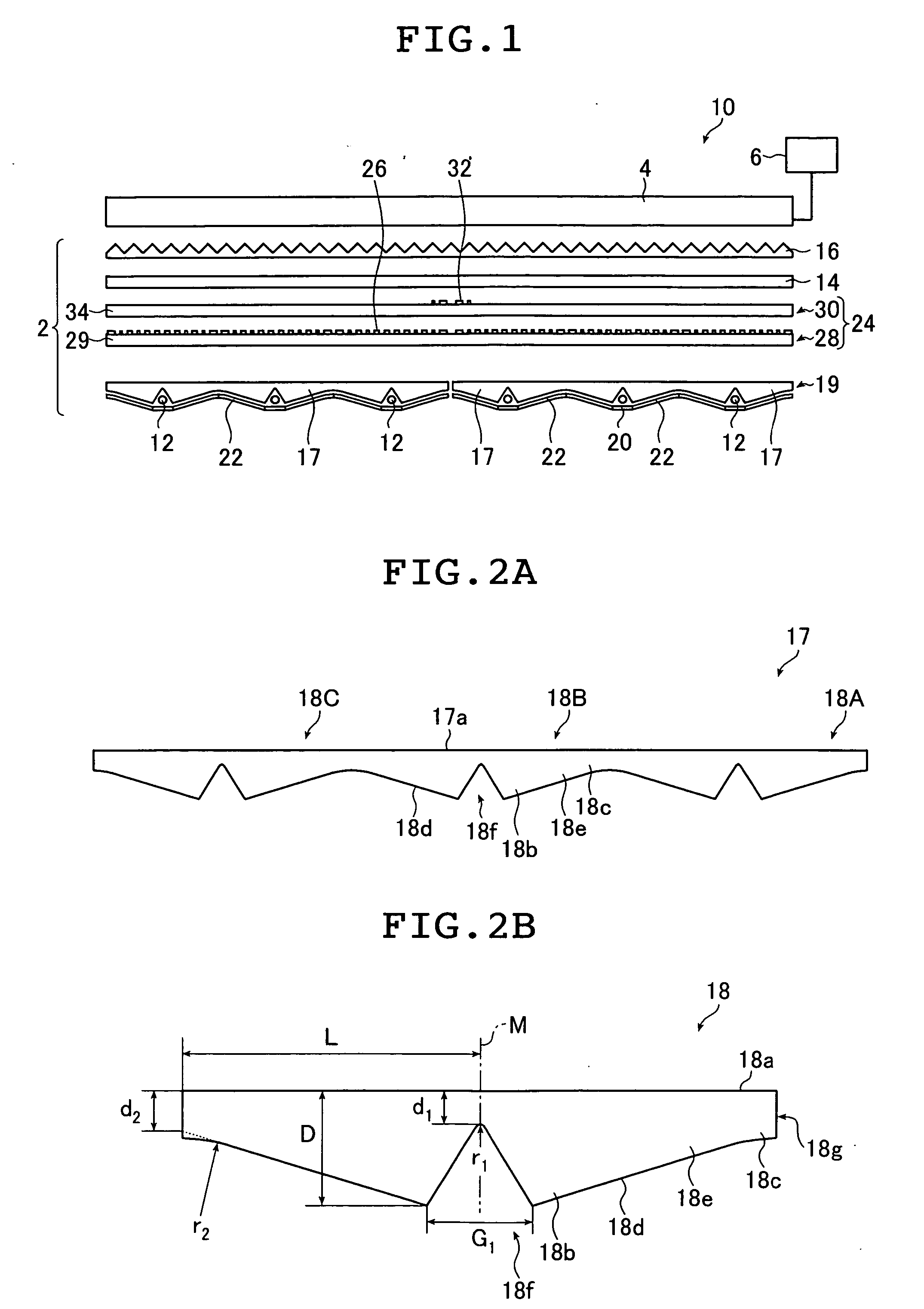
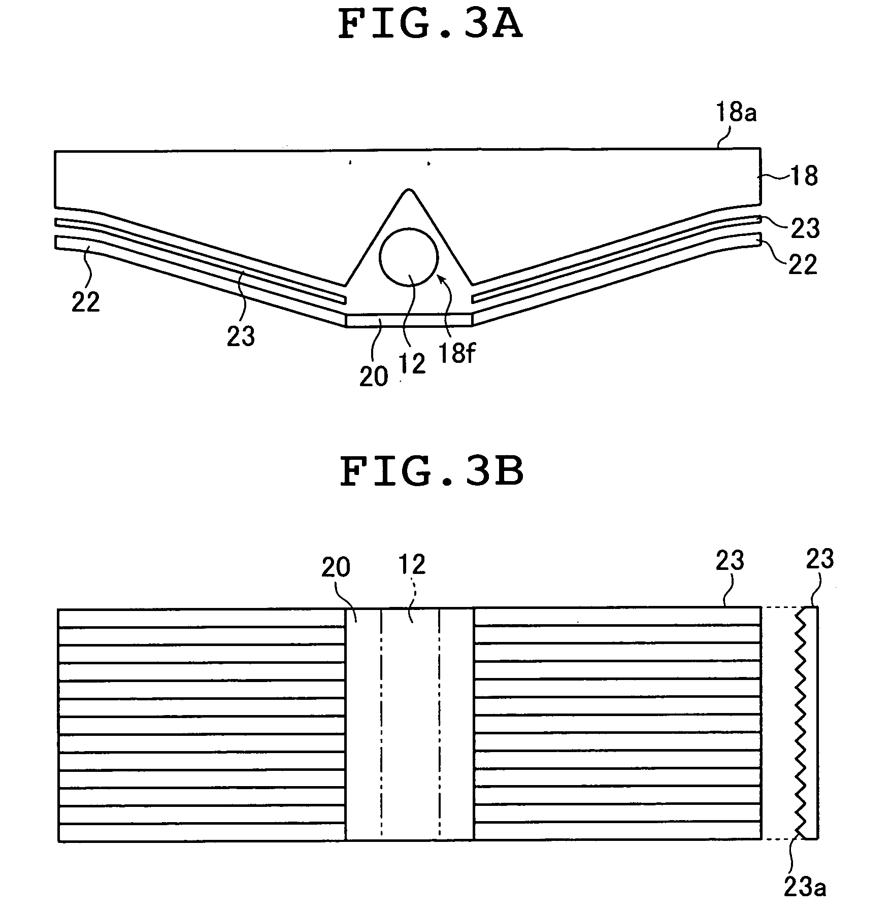
[0135] In this example, there was fabricated a backlight unit having the same structure as the backlight unit shown in FIG. 1. To be more specific, the backlight unit 2 of this example was composed of the light source 12, the diffusion film 14, the prism sheet 16, the light guide plate 19, the reflector 20, the reflective film 22, the first transmittance adjusting member 28, and the second transmittance adjusting member 30.

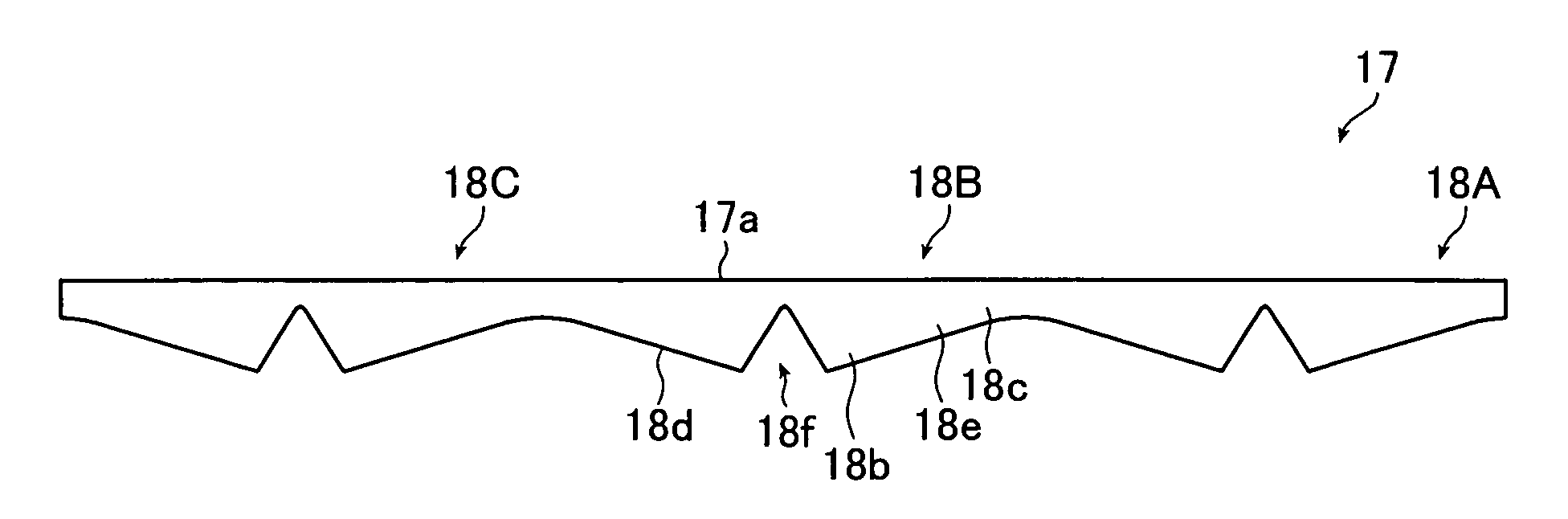
[0136] In this example, a cold cathode tube with a diameter R of 2.6 mm was used as the light source 12. The light guide plate unit 18 was of a shape having the following dimensions (see FIG. 2B): the distance L from the center of the light guide plate unit 18 to the face at which it was thinnest, or the face at which it joined to an adjacent light guide plate unit 18 was 14 mm; the thickness D of the thickest part of the thick-walled portion 18b of the light guide plate unit 18 was 5.5 mm; the distance d1 between the bottom portion of the parallel groove 18f and...


PUM


Abstract

The planar lighting device includes rod type light sources, a light guide plate having light guide plate blocks, each being formed of an integral assembly of at least two light guide plate units each having a rear surface with a groove formed to accommodate a rod type light source and a light exit surface that is away from the rear surface and which is for emitting the light from the light source and a transmittance adjuster unit that is provided on a side closer to the light exit surface, and which has a sheet type optical member capable of transmitting light and transmittance adjusters provided on at least one surface of the optical member. The transmittance adjusters at a position corresponding to a seam between adjacent light guide plate blocks are distributed at a different density than the transmittance adjusters at a position corresponding to a joint between adjacent light guide plate units.

Description

TECHNICAL FIELD The entire contents of the documents cited in this specification are incorporated herein by reference. [0001] The present invention relates to a planar lighting device for causing uniform planar light to be emitted from a light exit surface, and a liquid crystal display device using the same. BACKGROUND ART [0002] A liquid crystal display device is provided with a backlight unit for irradiating a liquid crystal panel (LCD) with light from its rear side and illuminating the liquid crystal panel. The backlight unit includes an illuminating light source, a light guide plate that diffuses light emitted from the light source to irradiate the liquid crystal panel with the light, a prism sheet or diffusion sheet for equalizing the light emitted from the light guide plate and other such components. [0003] A known example of such backlight unit is disclosed in JP 9-304623 A. [0004]FIG. 20 is a schematic sectional view of an area light source device disclosed in JP 9-304623 A...

Claims


Application Information

Patent Timeline
Patent Type & Authority Applications(United States)
IPC IPC(8): G09F13/04
CPCG02F1/133604G02F1/133606G09F13/04
Inventor MATSUSHITA, MOTOHIKO
Owner FUJIFILM CORP
Why Eureka
Try Eureka