
Semiconductor Device

Inactive Publication Date: 2007-06-28
SK HYNIX INC
View PDF4 Cites 49 Cited by
  • Summary
  • Abstract
  • Description
  • Claims
  • Application Information

AI Technical Summary

Benefits of technology

[0011]A multi-word line refresh-type semiconductor device performs a refresh operation simultaneously with respect to a plurality of word lines for each bank in a self-refresh mode, wherein redundancy word lines to replace word lines to be repaired are not installed separately in a plurality of blocks in each bank, but shared by the blocks, so that a chip area occupied by the redundancy word lines can be reduced, thereby securing economic efficiency of chip design and increasing repair efficiency of the redundancy word lines for failed word lines.

Problems solved by technology

With the advance of wireless communications and the development of various contents, a matter of reduction in power consumption of mobile products has become a very important issue.
In this regard, a matter of reduction in refresh current has become one important issue in dynamic random access memories (DRAMs).
For this reason, assuming that 8×1024 word lines are present in each bank, the series of control circuits must be operated 8×1024 times to refresh data in cells connected to all those word lines, resulting in a large amount of operating current being consumed.
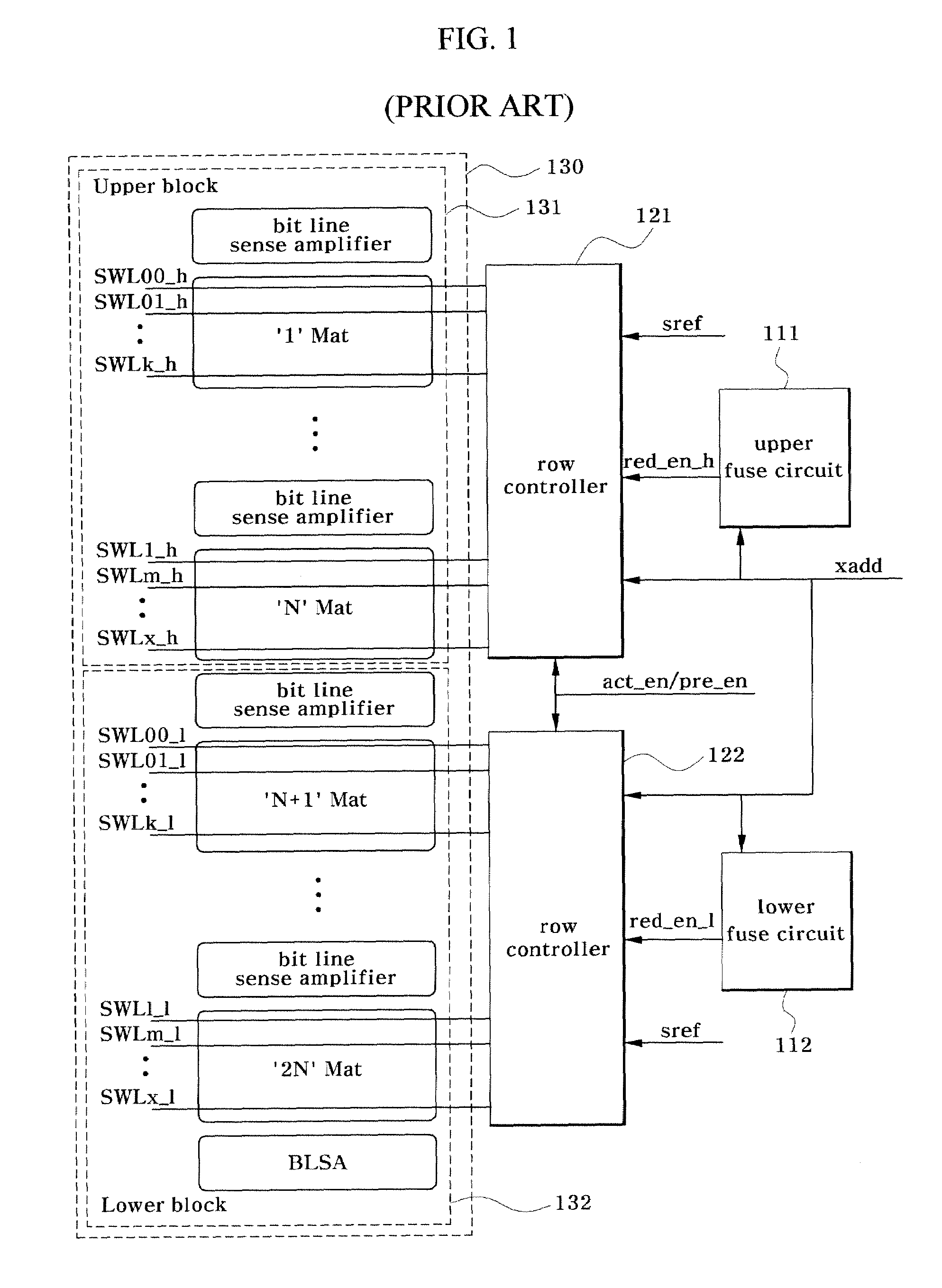
However, this multi-word line refresh-type semiconductor device has a problem as will be described below.
For this reason, the conventional semiconductor device has a disadvantage in that the number of redundancy word lines is increased, resulting in an increase in chip area.
It is also disadvantageous in that repair efficiency of each redundancy word line is reduced.

Method used


Image

  • Semiconductor Device
  • Semiconductor Device
  • Semiconductor Device

Examples


Embodiment Construction

[0053]Reference will now be made in detail to various embodiments of the present invention, examples of which are illustrated in the accompanying drawings, wherein like reference numerals refer to like elements throughout. The embodiments are described below to explain the present invention by referring to the figures.

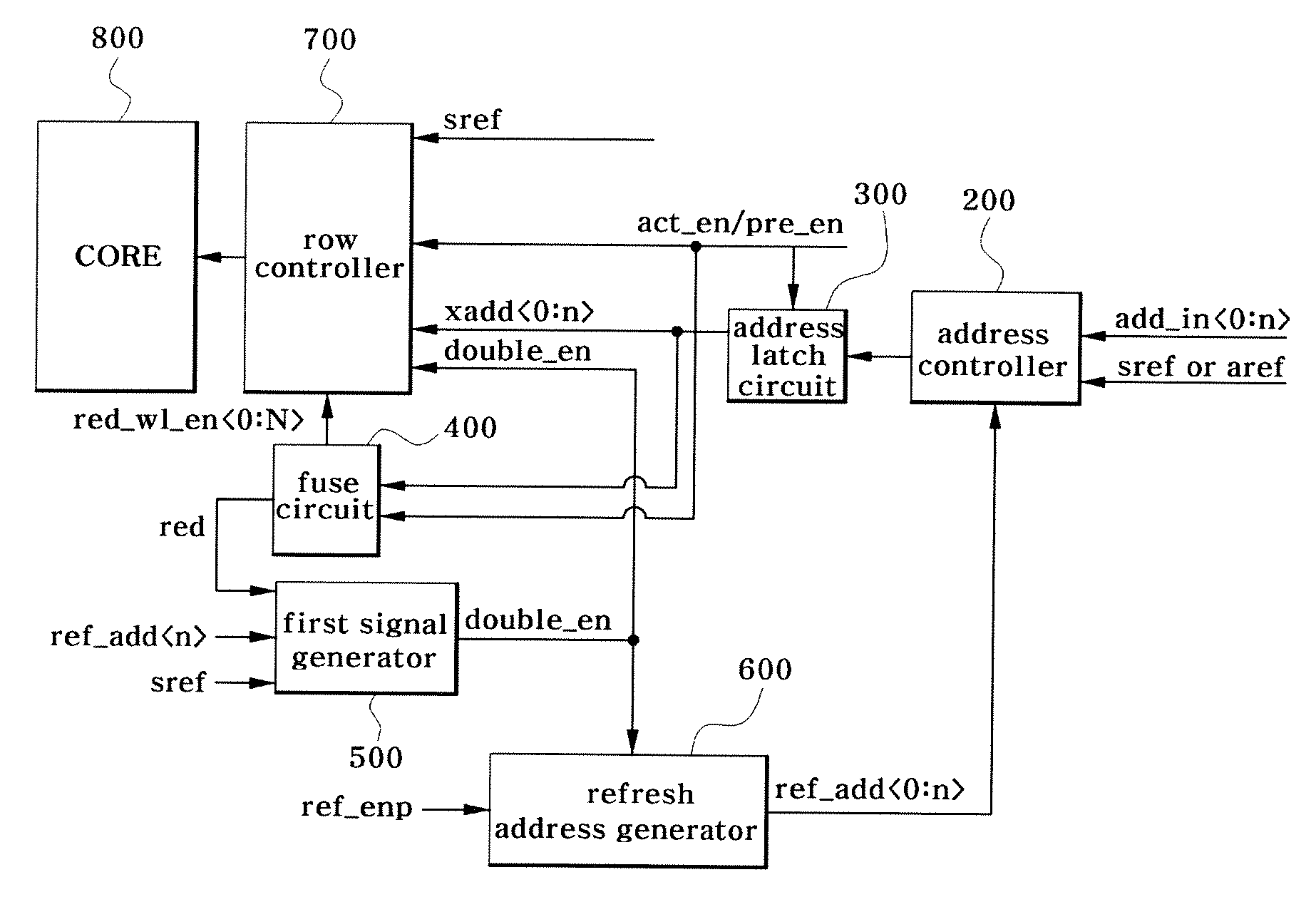
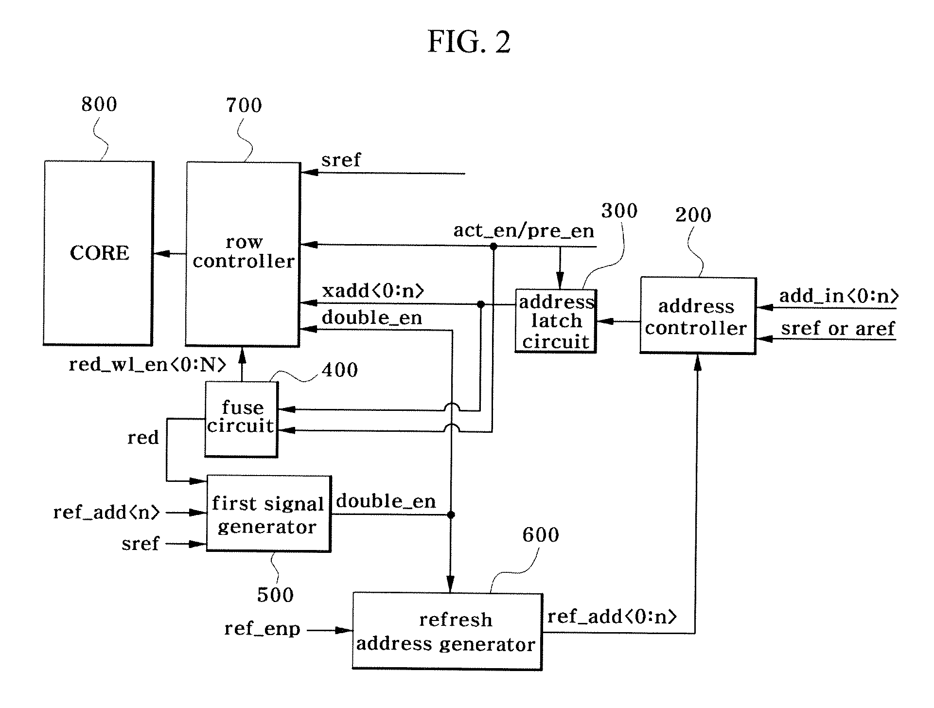
[0054]FIG. 2 is a block diagram showing the configuration of a semiconductor device according to an exemplary embodiment. The configuration of the semiconductor device according to this embodiment will hereinafter be described with reference to FIG. 2.

[0055]The semiconductor device according to the present embodiment is a multi-word line refresh-type semiconductor device which has a plurality of memory banks and performs a refresh operation simultaneously with respect to a plurality of word lines for each of the banks in a self-refresh mode. As shown in FIG. 2, the semiconductor device according to the present embodiment comprises an address controller 200 for receivin...


PUM


Abstract

A multi-word line refresh-type semiconductor device may have a plurality of memory banks and performs a refresh operation simultaneously with respect to a plurality of word lines for each of the banks in a self-refresh mode. The semiconductor device includes an address controller for receiving a normal address and a refresh address and selectively outputting the received refresh address in a refresh mode, a fuse circuit for receiving the refresh address, determining whether the received refresh address corresponds to a word line to be repaired and outputting a redundancy word line enable signal and a first control signal according to a result of the determination, a first signal generator for, in response to a bit value for block selection of the refresh address and the first control signal, outputting a second control signal which defines a multi-word line refresh period, a refresh address generator for generating the refresh address in response to the second control signal, and a row controller for receiving the refresh address, second control signal and redundancy word line enable signal and controlling the refresh operation with respect to a memory core.

Description

BACKGROUND[0001]1. Technical Field[0002]This patent relates to a semiconductor device, and more particularly to a multi-word line refresh-type semiconductor device for performing a refresh operation simultaneously with respect to a plurality of word lines for each bank in a self-refresh mode.[0003]2. Description of the Related Art[0004]With the advance of wireless communications and the development of various contents, a matter of reduction in power consumption of mobile products has become a very important issue. In this regard, a matter of reduction in refresh current has become one important issue in dynamic random access memories (DRAMs). The refresh operation of a semiconductor device, such as a DRAM, is classified into an auto-refresh type and a self-refresh type. In the refresh operation, the semiconductor device refreshes each word line of a memory core at a certain period appropriate to a refresh retention time of each cell in the memory core according to a given operation ...

Claims


Application Information

Patent Timeline
IPC IPC(8): G11C7/00
CPCG11C8/14G11C11/406G11C11/40611G11C11/40615G11C11/40618G11C11/4085G11C29/783G11C2211/4061G11C8/08
Inventor LEE, JONG WON
Owner SK HYNIX INC
Learn More