Cross layer optimization for improving TCP performance in lossy wireless environments

a wireless environment and cross-layer optimization technology, applied in data switching networks, frequency-division multiplexes, instruments, etc., can solve the problems of serious impact on repeated aborting of the recovery procedure, and severe reduction of the throughput of the source, so as to reduce the loss of packets

Inactive Publication Date: 2007-06-28
PANASONIC CORP
View PDF11 Cites 14 Cited by
  • Summary
  • Abstract
  • Description
  • Claims
  • Application Information

AI Technical Summary

Benefits of technology

[0004] In accordance with the present invention, an improved method is provided for reducing packet loss using cross layer information. In one aspect of the invention, the method includes: monitoring a transmission state of a data source, where the transmission state is defined in accordance with TCP's internal state machine; marking data packets with a pre-defined code (e.g., drop preference) at an Internet Protocol (IP) layer of the data packets based on the transmission state; and transmitting the marked data packets from the data source. The code used for marking in the IP header of the data packet conveys the requested handling of the packet at intermediate routing or forwarding entities. In a preferred embodiment, this code may indicate drop preference for the packet with regards to packets from other sources.

Problems solved by technology

The packet drops in the path severely reduce the throughput of a TCP source since a packet drop is seen an indication of network congestion.
Multiple packet losses in a short duration may result in repeated aborting of the recovery procedure, and restarting it again from the initial state of transmission window of just one packet.
This can have very serious impact on the throughput of a source.
However, currently there is no procedure in the current art that lets a TCP source minimize multiple packet losses, and hence avoid the resulting drastic throughput reduction.
This inability of the TCP data source may cause unfair distribution of bandwidth among competing sources, especially when a network link is congested and an intermediate routing node can only accommodate a limited amount of network traffic.
As a result this node can suffer unduly while other nodes may not see any packet loss at all.

Method used


Image

  • Cross layer optimization for improving TCP performance in lossy wireless environments
  • Cross layer optimization for improving TCP performance in lossy wireless environments
  • Cross layer optimization for improving TCP performance in lossy wireless environments

Examples


Embodiment Construction

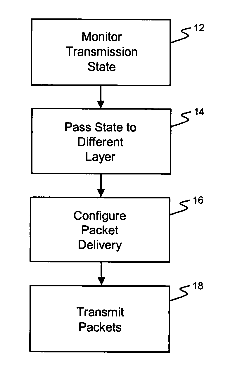
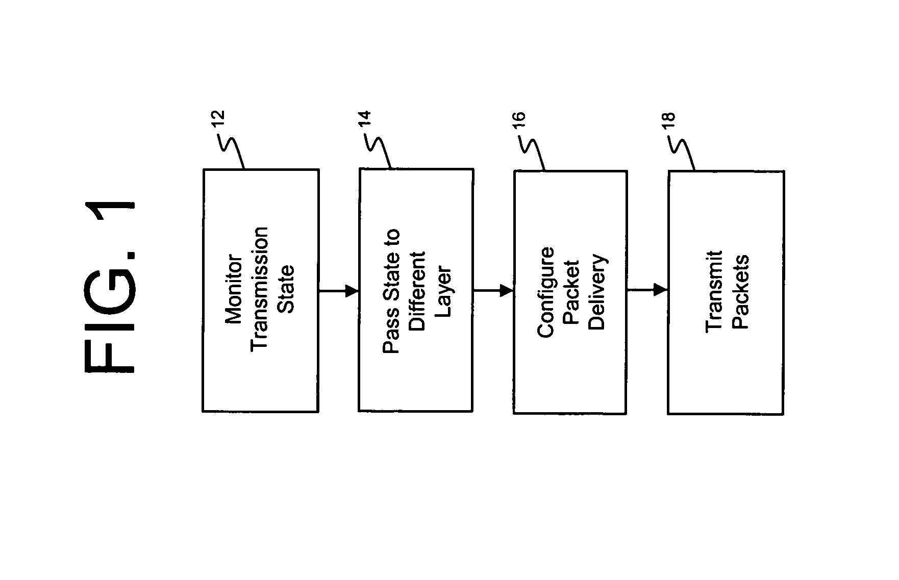
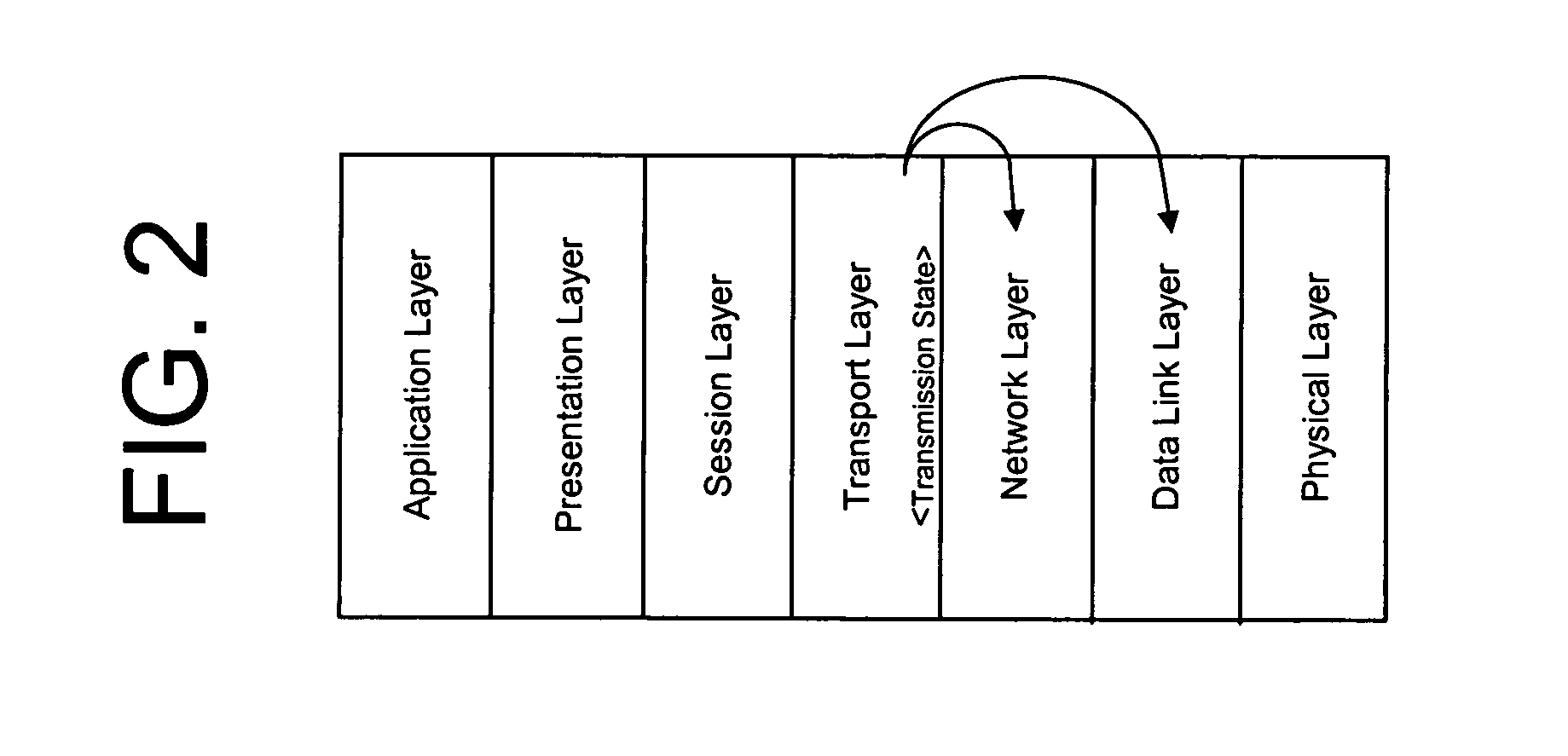
[0010]FIG. 1 illustrates a method for reducing packet loss using cross layer information according to the principles of the present invention. In general, a transmission state of a network data source is monitored at step 12, where the transmission state is defined by a communication protocol operating at a transport layer of an Open System Interconnection (OSI) model. The transmission state is then passed at 14 from the transport layer to a layer below the transport layer (e.g., the network layer or data link layer) as defined by the OSI model. In step 16, data packet delivery parameters are configured at the lower layer based on the transmission state received from the transport layer prior to the packets being sent across the network at step 18. In this way, the network can provide fairer distribution of bandwidth amongst data source competing for congested links.

[0011] Transport Control Protocol (TCP) is a well known communication protocol that operates at the transport layer (...


PUM


Abstract

An improved method is provided for reducing packet loss using cross layer information. An exemplary method includes: monitoring a transmission state of a data source, where the transmission state is defined in accordance with TCP; marking data packets with a drop preference at an Internet Protocol (IP) layer of the data packets based on the transmission state; and transmitting the marked data packets from the data source.

Description

FIELD OF THE INVENTION [0001] The present invention relates to improving TCP performance and, more particularly, to a method for reducing packet loss using cross layer information during data transfer. BACKGROUND OF THE INVENTION [0002] Transport control protocol (TCP) uses several mechanisms to avoid congestion, including slow start, congestion avoidance, fast retransmit and recovery, and selective acknowledgement. The packet drops in the path severely reduce the throughput of a TCP source since a packet drop is seen an indication of network congestion. A TCP source, after detecting a packet loss, employs a slow start and congestion avoidance procedure to limit the rate at which packets are sent to the network. A TCP source's internal parameter, transmission window size, controls the number of outstanding unacknowledged packets in the communication pipe between a sender and the receiver. Every time a packet is dropped in the path, a TCP source must follow the slow start and congest...

Claims


Application Information

Patent Timeline
Patent Type & Authority Applications(United States)
IPC IPC(8): H04J1/16H04L12/56
CPCH04L1/187H04L47/10H04L47/14H04L47/193H04L47/31H04L47/32H04W80/06H04W28/10H04W8/04
Inventor KUMAR, BRIJESH
Owner PANASONIC CORP
Why Eureka
Try Eureka