Method of bandwidth control by rewriting ACK number

a bandwidth control and ack number technology, applied in the field of packet relay apparatus, can solve the problems of reduced throughput, packet loss might have occurred on a transmission line, and limited use of access lines that provide bidirectional transmission capacity of 10 mbps, so as to reduce packet loss, ensure audio quality, and reduce the downstream throughput of tcp communication

Inactive Publication Date: 2010-03-09
PANASONIC CORP
View PDF7 Cites 1 Cited by
  • Summary
  • Abstract
  • Description
  • Claims
  • Application Information

AI Technical Summary

Benefits of technology

[0040]The present invention is provided to address the above-noted shortcomings. An object of the present invention is to lower downstream throughput of TCP communication other than voice communication without depending on a window size, so as to ensure audio quality.
[0041]The present invention relates to a network relay apparatus connecting with a first terminal and a second terminal, the network relay apparatus comprising a transmitter that transmits first data received from the first terminal to the second terminal and transmits second data received from the second terminal to the first terminal, the second data comprising acknowledgement information according to the first data, and a data modifier that modifies the second data to change the acknowledgement information into an another acknowledgement information, wherein said transmitter transmits the modified second data to the first terminal. In the configuration, downstream throughput of a TCP packet does not exceed a capacity of the network, thus reducing packet loss when a voice communication packet and the like are transmitted simultaneously.

Problems solved by technology

A packet loss might have occurred on a transmission line in this case.
Under the circumstance, a number of packet losses occur in the method, and thus the throughput declines.
Although a transmission capacity of an access line to a home over ADSL or CATV has been increasing year after year, use of an access line that provides a bidirectional transmission capacity of 10 Mbps, such as the Ethernet, is still limited.
When the transmission amount exceeds the transmission capacity, a packet transmission queue or a packet reception queue of access router D2 is extended to a maximum length, thus causing a packet loss.
In addition, as the transmission amount on upper level transmission line D3 approaches the transmission capacity due to the TCP segment, jitter of the voice communication packet (refer to Publication 1, for example) generally becomes large, which also has a significant impact on the audio quality.
It is difficult for access router D2, however, to control the downstream throughput, since upper level relay apparatus D6 transmits the TCP segment and the voice communication packet.
Thus, the technology of Related Art 1 is not effective for the client incapable of processing the window size.
With the technology, the downstream throughput of the TCP communication except of the voice communication cannot be lowered purposely, and thus the audio quality cannot be ensured.

Method used


Image

  • Method of bandwidth control by rewriting ACK number
  • Method of bandwidth control by rewriting ACK number
  • Method of bandwidth control by rewriting ACK number

Examples


first embodiment

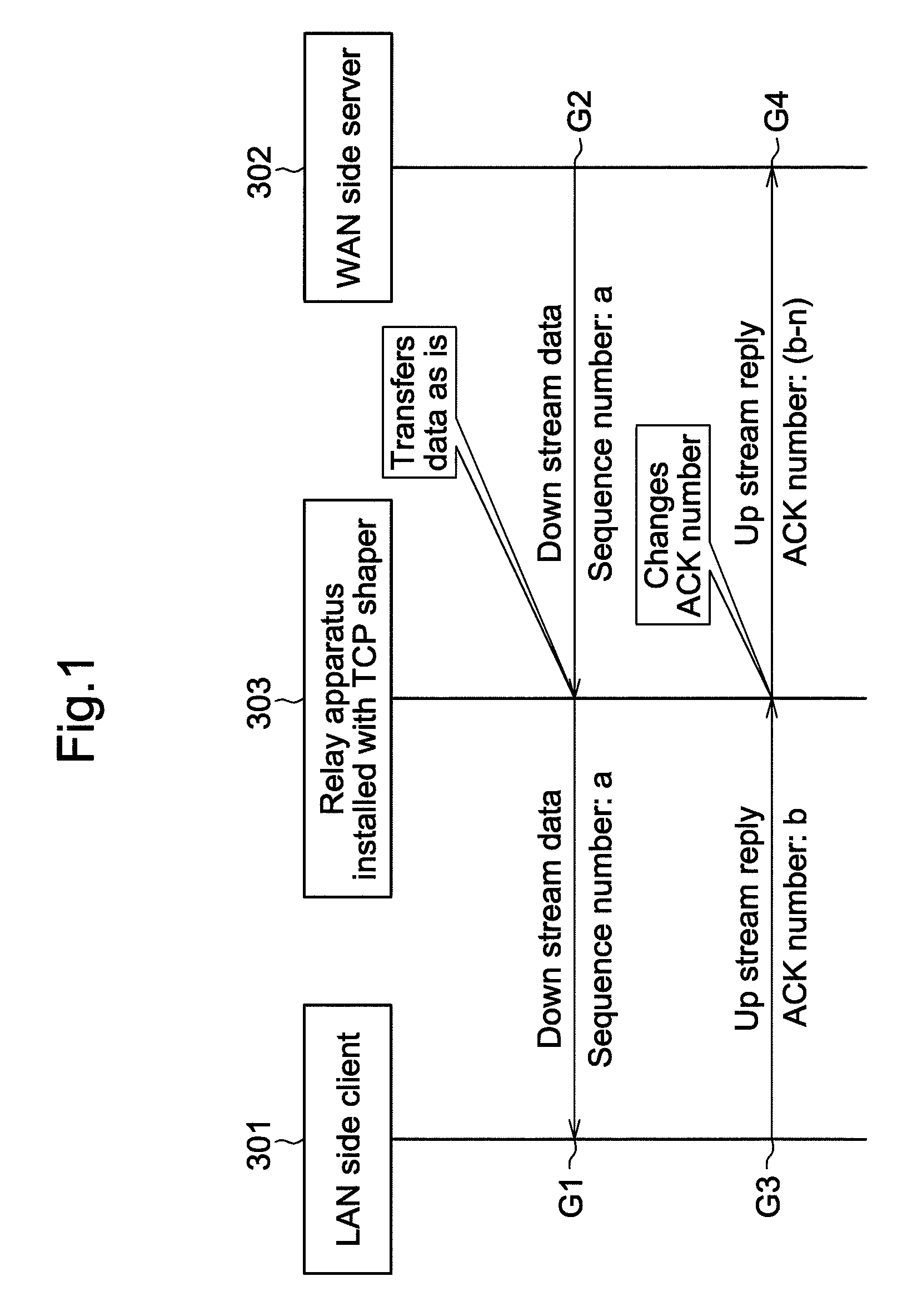
[0073]In a first embodiment, descriptions are provided in order of: a basic operation concept of the present invention with reference to FIG. 1; a configuration of a basic TCP shaper with reference to FIGS. 3 to 5; a process flow of each module included in the basic TCP shaper with reference to FIGS. 6 to 9; an operation example of the basic TCP shaper in “congestion avoidance mode” with reference to FIGS. 10 and 11; and an operation example of the basic TCP shaper in “slow start mode” with reference to FIGS. 12 and 13.

[0074]FIG. 1 illustrates the basic operation concept of the present invention. In FIG. 1, LAN side client 301 and WAN side server 302 communicate each other using TCP. Relay apparatus 303 installed with the TCP shaper is provided on a communication path between LAN side client 301 and WAN side server 302. An upstream direction herein indicates a direction from relay apparatus 303 installed with the TCP shaper to the WAN side server. A transmission line between relay a...

second embodiment

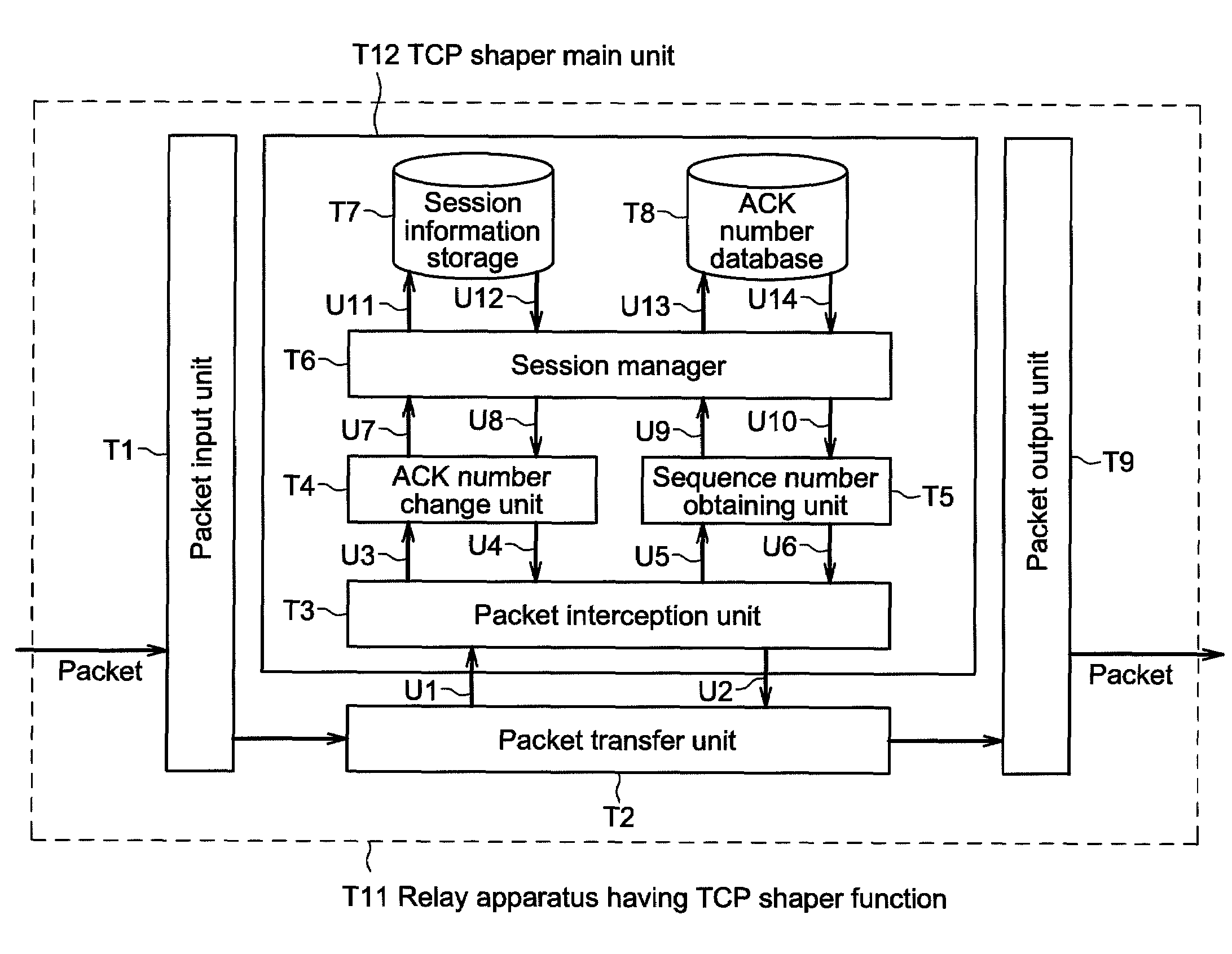
[0194]In a second embodiment, descriptions are provided in order of: a difference from the first embodiment; a configuration of an enhanced TCP shaper with reference to FIGS. 14 to 15; a process flow of each module included in the enhanced TCP shaper with reference to FIG. 16; and an operation example of the enhanced TCP shaper with reference to FIGS. 17 and 18.

[0195]In the first embodiment, a packet containing TCP data is relayed only in a direction from server 404 to client 405 (a downstream direction) in TCP communication between server 404 and client 405 as shown in FIG. 12, for example. When client 405 transmits to server 404 a packet containing TCP data, TCP shaper relay apparatus 406 drops the packet containing TCP data and does not relay the packet to the server.

[0196]On the Internet these days, a server and a client sometimes exchange TCP data bidirectionally in a TCP session. For instance, to display contents stored on a web server using a web browser installed on an infor...

third embodiment

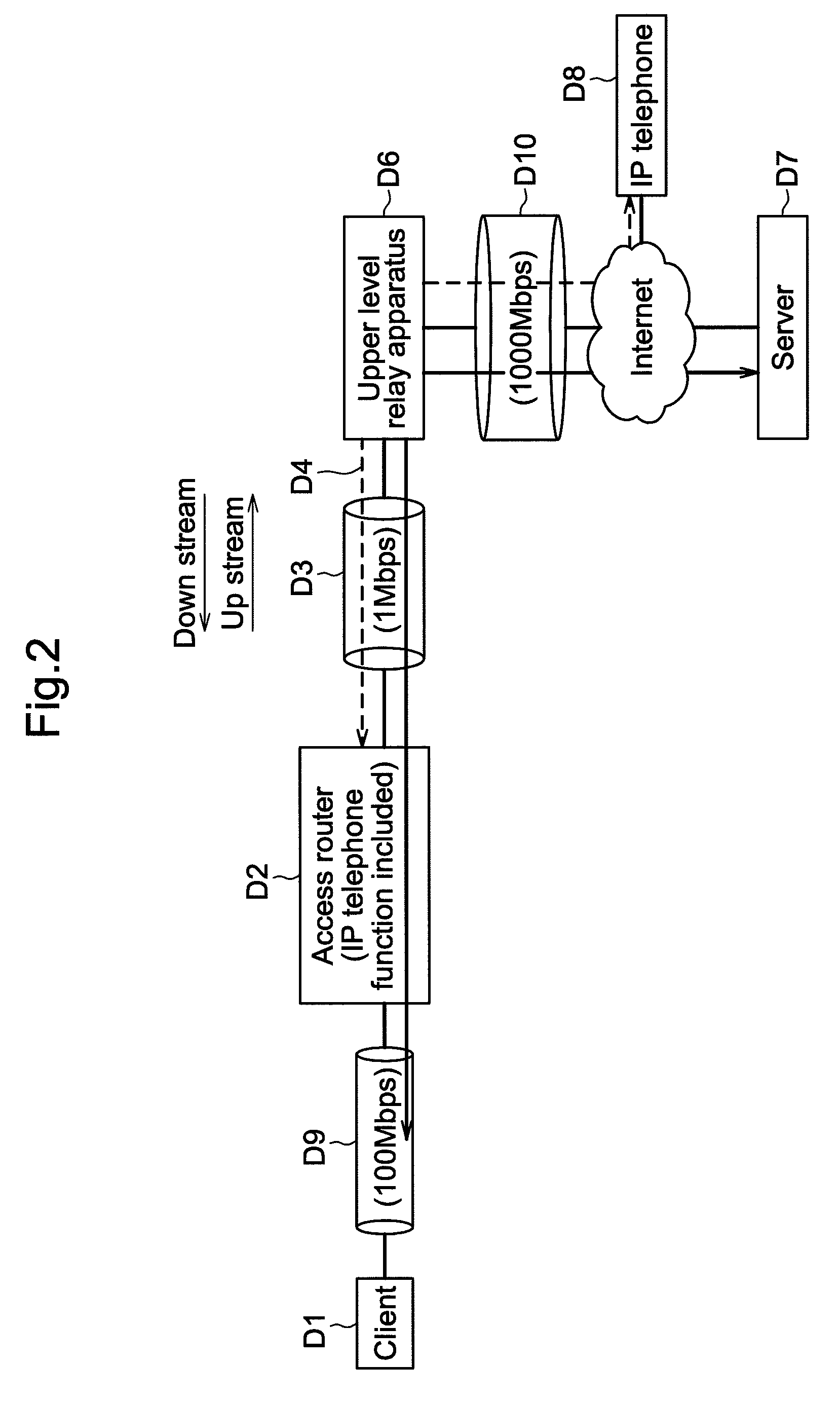
[0266]FIG. 2 shows an example in which a TCP shaper operates as one function of an access router.

[0267]In FIG. 2, client D1 indicates an information device, such as a home PC and the like. Access router D2, to which the present invention is applied, is a packet relay apparatus that relays a packet transmitted from client D1 to upper level relay apparatus D6 hereinafter described, and that relays a packet transmitted from upper level relay apparatus D6 to client D1. Access router D2 also has an IP telephone function, and transmits and receives a packet containing audio data (hereinafter referred to as an “audio packet”). Access router D2 is physically installed at a home. Further, access router D2 assigns an address to client D1 using DHCP (Dynamic Host Configuration Protocol). Access router D2 stores therein the IP address assigned with DHCP, and thus is capable of recognizing the IP address of client D1 all the time.

[0268]Client D1 and access router D2 are connected via transmissio...


PUM


Abstract

A network relay apparatus installed with a TCP shaper has a packet converter that changes an ACK number of a confirmation reply packet in response to downstream data transmitted from a WAN side host to a lower value while transferring the packet.

Description

BACKGROUND OF THE INVENTION[0001]1. Field of the Invention[0002]The present invention relates to a packet relay apparatus connected to a packet network such as the Internet.[0003]2. Description of Related Art[0004]With the widespread use of the Internet in recent years, a variety of communication protocols have been in use. A protocol layer called a transport layer includes TCP (Transmission Control Protocol) and UDP (User Datagram Protocol). TCP achieves reliable data transmission.[0005]FIG. 19 shows a TCP segment structure. TCP segment 102 is included in IP packet (hereinafter simply referred to as “packet”) 101. TCP segment 102 includes TCP header 103 and TCP data 104. TCP data 104 may contain no actual data.[0006]FIG. 28 shows an IP header 500 structure. Protocol number field 501 in IP header 500 contains a number for identifying a protocol in a transport layer included in a packet. For instance, when the protocol in the transport layer included in a packet having IP header 500 ...

Claims


Application Information

Patent Timeline
Patent Type & Authority Patents(United States)
IPC IPC(8): G06F15/16G06F15/173H04L47/22H04L47/2416H04L47/265
CPCH04L69/16H04L69/163
Inventor MOCHIDA, KEIHOMMA, HIDEKI
Owner PANASONIC CORP
Why Eureka
Try Eureka