Filter coefficient adjusting circuit

a filter coefficient and filter technology, applied in the field of filter coefficient adjusting circuits, can solve the problems of jitter characteristics of the pll circuit b>118/b> deterioration, complicated control, etc., and achieve the effects of optimizing the group delay of the reproduced signal, improving reproduction performance, and simplifying control techniqu

Inactive Publication Date: 2007-06-28
PANASONIC CORP
View PDF6 Cites 14 Cited by
  • Summary
  • Abstract
  • Description
  • Claims
  • Application Information

AI Technical Summary

Benefits of technology

[0035] According to the filter coefficient adjusting circuit of the present invention, it is possible to simplify the control technique as well as optimize the group delay of th...

Problems solved by technology

First, when it is attempted to have a loop construction that successively changes the tap coefficients of the digital equalizer filter 121 using the difference value between the output of the digital equalizer filter 121 and an ideal value, it is required for this loop and the PLL for extracting clocks to perform a double-loop operation, thereby resulting in a complicated control...

Method used


Image

  • Filter coefficient adjusting circuit
  • Filter coefficient adjusting circuit
  • Filter coefficient adjusting circuit

Examples


embodiment 1

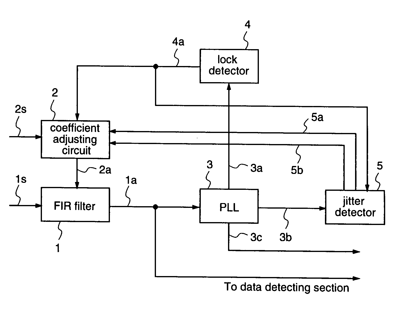
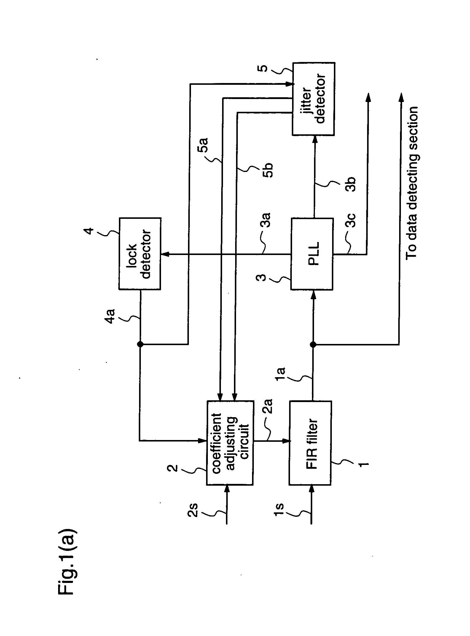
[0090] A filter coefficient adjusting circuit according to a first embodiment of the present invention will be hereinafter described, with reference to FIG. 1. FIG. 1(a) shows a structure of a filter coefficient adjusting circuit according to the first embodiment.

[0091] The filter coefficient adjusting circuit as shown in FIG. 1(a) comprises a FIR filter 1 which makes an inputted reproduced signal 1s subjected to a filtering processing employing an equalization coefficient, a PLL 3 which extracts clocks 3c which are synchronized with the reproduced signal on the basis of an output 1a of the FIR filter 1, a lock detector 4 which detects a lock state of the PLL 3, an equalization performance detecting means (jitter detector) 5 which detects an equalization performance of the FIR filter 1, and an equalization coefficient determining means (coefficient adjusting circuit) 2 which determines an equalization coefficient sequence 2a of the FIR filter 1 according to the output value 5a from...

embodiment 2

[0106] A filter coefficient adjusting circuit according to a second embodiment of the present invention will be described hereinafter, with reference to FIGS. 1-3 and FIGS. 6-7. Since FIGS. 1-3 are described in the first embodiment, the explanations thereof are omitted here.

[0107]FIG. 6(a) is a diagram illustrating a detailed structure of the asymmetry ratio determining circuit 201 in the coefficient adjusting circuit 2 of FIG. 3.

[0108] The asymmetry ratio determining circuit 201 as shown in FIG. 6(a) includes a jitter value capturing section 301 which captures a jitter value 5a which is outputted from the jitter detector 5, a controller section 302 which generates a control signal within the coefficient adjusting circuit 2, a minimum value detecting section 303 which detects the minimum value of the jitter values 301a which are captured into the jitter value capture section 301 and retains an asymmetry ratio at that time, an asymmetry ratio update section 304 which updates the as...

embodiment 3

[0126] A filter coefficient adjusting circuit according to a third embodiment of the present invention will be hereinafter described, with reference to FIGS. 1˜3 and 9. As FIGS. 1˜3 have been already described in the first embodiment, the explanations thereof are omitted here.

[0127]FIG. 9 is a diagram illustrating a structure of the multiplier section 202 in the coefficient adjusting circuit 2 in FIG. 3.

[0128] The multiplier section 202 as shown in FIG. 9 includes a selection signal generating section 503 which generates a select signal 503a and an enable signal 503b on the basis of the timing signal 201c which is outputted from the asymmetry ratio determining circuit 201, a multiplexer 501 which selects one among equalization coefficient initial values 11a˜14a on the basis of the select signal 503a, a multiplexer 502 which selects one among equalization coefficient initial values 15a˜19a on the basis of the select signal 503a, a multiplier 504 which multiplies the output from the...


PUM


Abstract

A filter coefficient adjusting circuit of the present invention comprises a coefficient adjusting circuit (2) that adjusts an equalization coefficient by weighting an initial value of the equalization coefficient on the left side from a center tap of a FIR filter (1) that equalizes a reproduce signal, by a factor of n, and weighting an initial value of the equalization coefficient on the right side by a factor of (2−n), and determines the factor n of the weighting so as to optimize an output of a jitter detector (5), for example, that detects jitter between the reproduced signal and a clock, as an equalization performance detecting means that detects an equalization performance of the reproduce signal. According to the filter coefficient adjusting circuit of the present invention, it is possible to simplify the control method as compared to conventional group delay correcting circuits, and optimize the group delay of the reproduced signal according to the characteristics of the reproduced signal without requiring any additional circuits, thereby improving the reproduction performance.

Description

TECHNICAL FIELD [0001] The present invention relates to a recorded information reproducing apparatus that reproduces data from recording media such as optical discs employing a FIR (Finite Impulse Response) filter and, more particularly, to a filter coefficient adjusting circuit that corrects group delay distortion of reproduced signals by means of the FIR filter. BACKGROUND ART [0002]FIG. 10 illustrates a common recorded information reproducing apparatus, taking a DVD as an example. [0003] The recorded information reproducing apparatus as shown in FIG. 10 has a recording medium 111, an AGC (Automatic Gain Control) circuit 112, an analog equalizer filter 113, an offset adjusting circuit 114, an A / D converter 115, an adaptive FIR filter 116, a Viterbi decoder 117, and a PLL (Phase Locked Loop) circuit 118. [0004] Functions of the respective components of the apparatus will be briefly described. [0005] The AGC circuit 112 and the offset adjusting circuit 114 adjust the amplitude and o...

Claims


Application Information

Patent Timeline
IPC IPC(8): H03K5/159H04L7/00G11B20/10G11B20/14H03H17/02H03H17/06H03H21/00H04L25/03
CPCH03H17/0227H03H17/0294H03H21/0012H04L25/03038
Inventor OKAMOTO, KOUJINAKAHIRO, HIROYUKI
Owner PANASONIC CORP
Why Eureka
Try Eureka