
Vehicle and equipment transport vehicle

a technology for vehicles and equipment, applied in the field of truck beds, can solve the problems of difficult to deliver on muddy construction sites with such truck-trailer combinations, long truck-trailer combinations, and high cost of single delivery of small units, so as to reduce the cost of post assembly, improve the effect of simplified post assembly or locking post design

Inactive Publication Date: 2007-06-28
METALCRAFT OF MAYVILLE
View PDF58 Cites 0 Cited by
  • Summary
  • Abstract
  • Description
  • Claims
  • Application Information

AI Technical Summary

Benefits of technology

[0007] In one embodiment of the present invention, each deck section of the bed is constructed in an arch. The result is a light weight bed of great strength without need for a number of heavy gauge cross pieces as is typical in conventional flat bed design. An additional benefit of this design is that the resultant lowered center of gravity of both the bed and the load provides improved handling and a sense of greater stability for the driver.
[0008] In another embodiment, when in the travel position, the arch of the rear deck is slightly higher than that of the front. The benefit of this feature is that no significant hump occurs at the hinge line when the rear deck is lowered for ground loading and unloading. This allows very easy loading of any equipment with low ground clearance without fear of bottoming out on the hinge when crossing from the rear to the front portion of the deck.
[0009] In another embodiment, the rear deck-ramp combination of the present invention creates a very gentle grade, low enough to allow most powered equipment to readily climb onto the deck without assistance from a winch, thus reducing the cost of loading by saving time and labor.
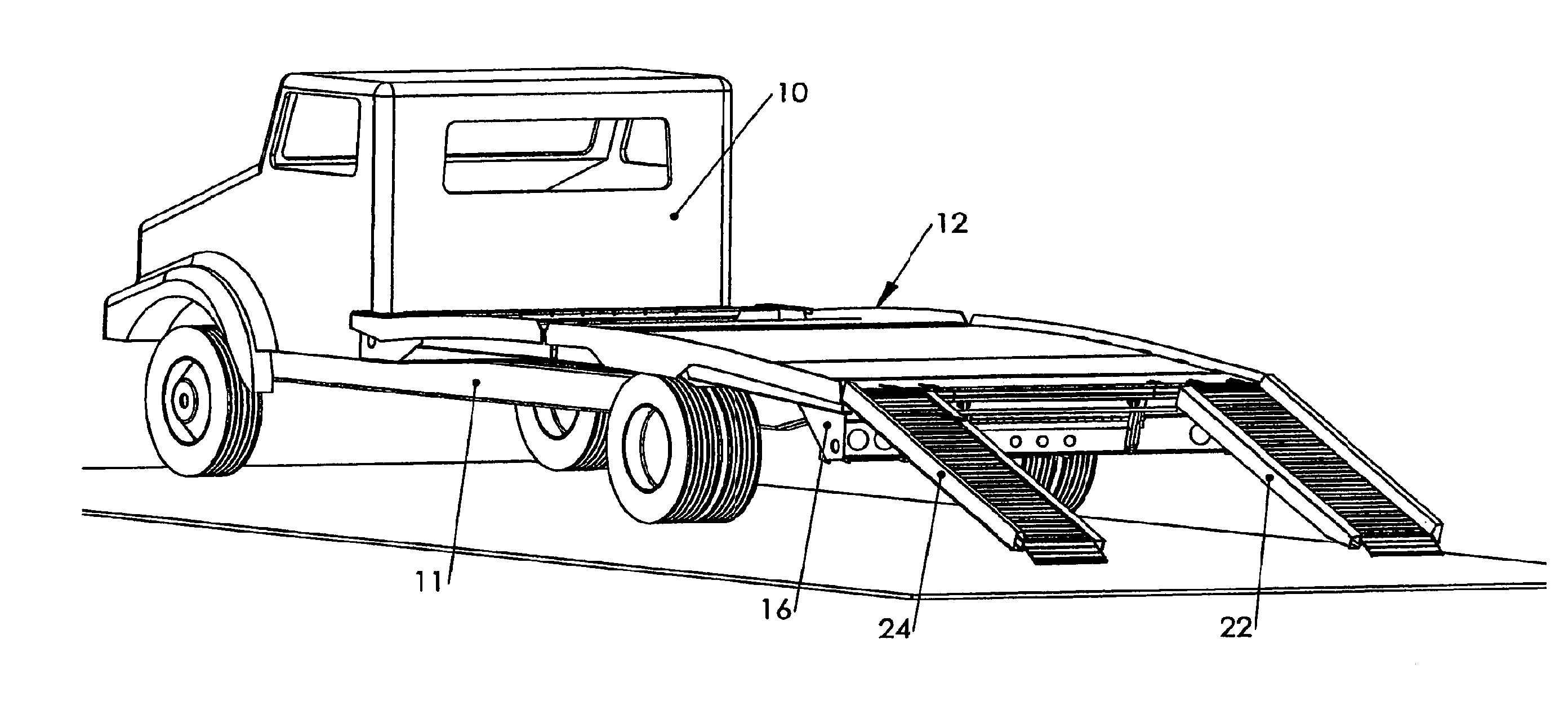
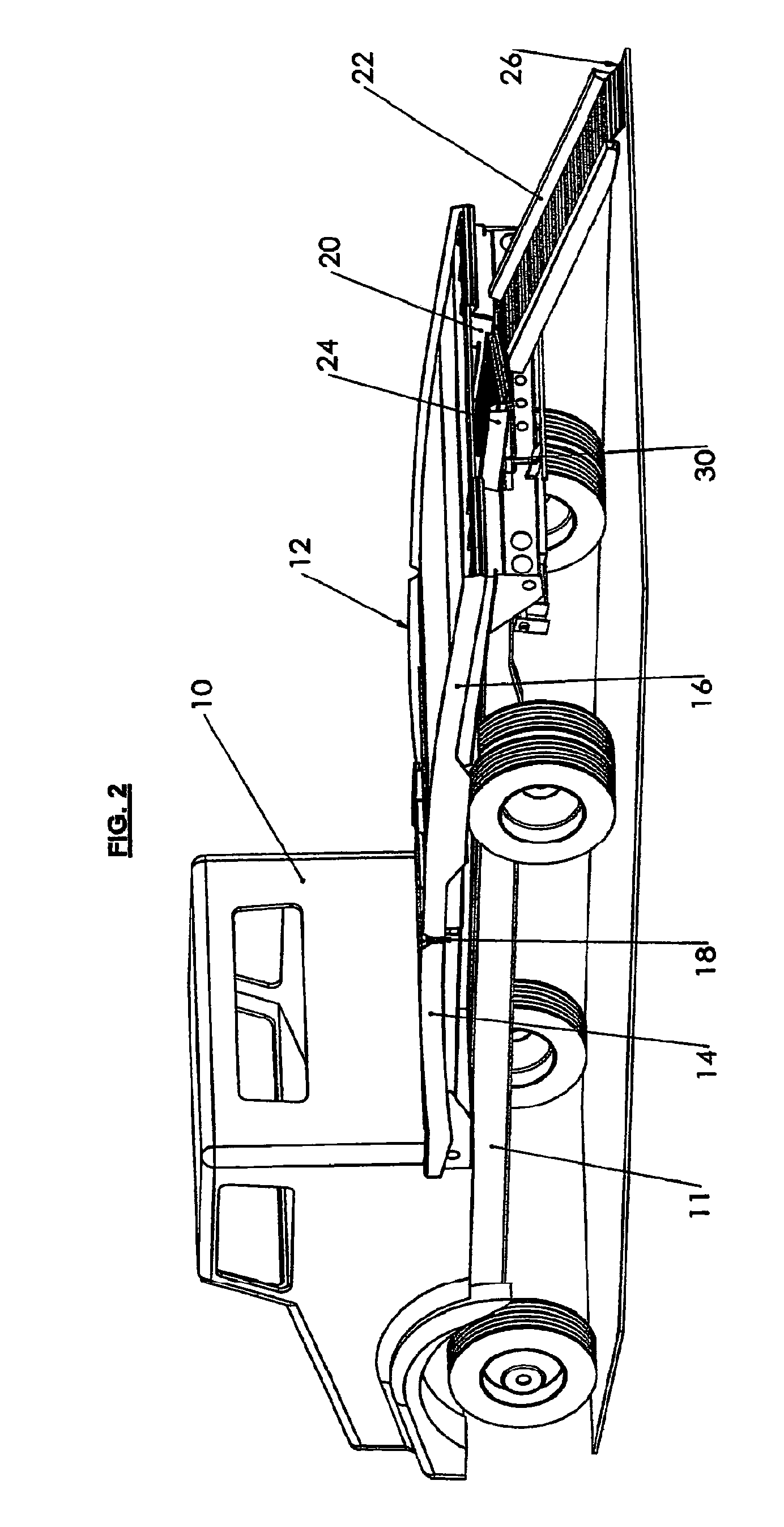
[0010] In still yet another embodiment, the front deck portion is firmly fixed to the truck frame with conventional “U” bolts and shear plates. In the travel position, the hinge mounted rear deck is carried on two posts whose top ends are mounted to the deck frame while the slotted bottom end rests in truck frame mounted pins. The rear deck can be moved through an arc by a frame mounted elevating device such as an air or hydraulic cylinder, or by a powered screw. Ideally, the elevating device does not carry any load while the bed is in the travel position. This movement allows the rear deck to be raised for loading and unloading to an elevated dock, or lowered for loading and unloading directly to the ground. The rear deck also has a storage apparatus for ramps. These are used as a length addition to the lowered rear deck for ground loading and unloading. The rear deck-ramp combination creates a very gentle grade, low enough to allow most powered equipment to readily climb onto the deck without assistance from a winch, thus saving labor and time in loading the truck bed.
[0013] In yet another embodiment of the present invention, the truck bed of the present invention has an improved and simplified post assembly or locking post design. This improved post assembly reduces the cost of the post assembly in the embodiments described above. In a further embodiment, the post assembly is provided with a notched dock lock to support the rear deck of the truck bed at a height convenient for loading or unloading equipment from a commercial truck dock.

Problems solved by technology

This has made the single delivery of a small unit very costly to the distributor since he cannot pass on the full expense to his customer.
Even a small truck-trailer combination is quite long and difficult to maneuver for all but a skilled operator, especially in crowded city traffic.
Delivery on muddy construction sites with such truck-trailer combinations is extremely difficult, especially when backing up to a drop off site is required.

Method used


Image

  • Vehicle and equipment transport vehicle
  • Vehicle and equipment transport vehicle
  • Vehicle and equipment transport vehicle

Examples


Embodiment Construction

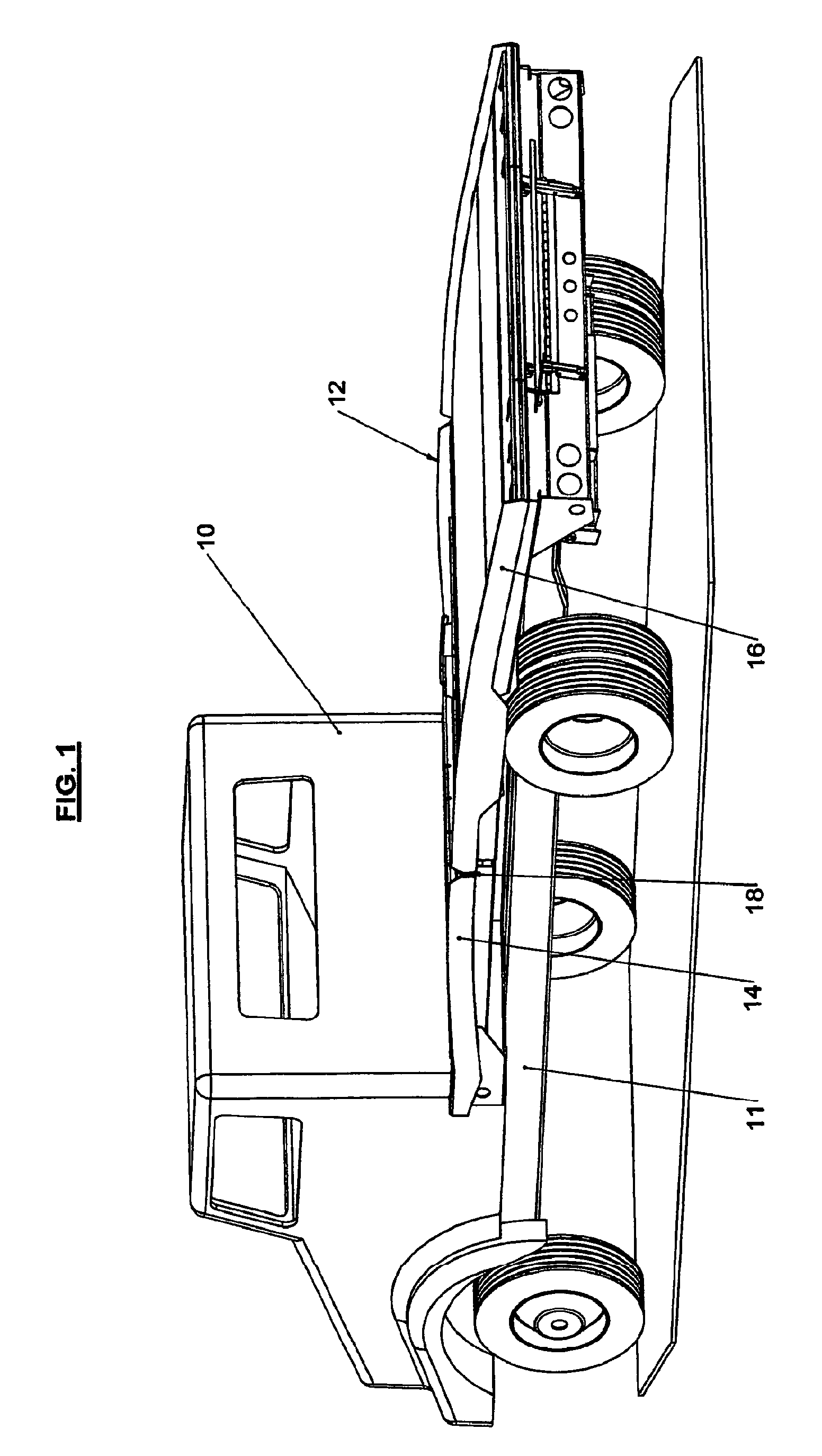
[0036] In the accompanying drawings, FIG. 1 shows an unloaded truck 10 with a truck frame 11 and a truck bed 12 of the present invention in a travel position. The truck bed 12 has a front deck portion 14 and a rear deck portion 16. In a preferred embodiment, the front deck portion 14 and the rear deck portion 16 are each constructed in the form of an arch, as shown in FIGS. 1, 2, 4, 5, 6 and 7. In a further preferred embodiment, when in the travel position, the arch of the rear deck portion 16 is slightly higher than that of the front bed portion 14. A transverse hinge 18 preferably connects the front deck portion 14 and the rear bed portion 16.

[0037] Preferably, the front deck portion 14 is firmly fixed to the truck frame 11. This connection can be made with, but is not limited to, “U” bolts and shear plates. In the travel position, the hinge mounted rear deck 16 is preferably carried on a two-post assembly 40 whose top ends are pinned to cross beam assembly 41 at 42. The closed l...


PUM


Abstract

The present invention is directed to a specialized truck bed wherein the bed is divided into two areas or deck sections connected by a transverse hinge. The invention is also directed to a winch system for use on a vehicle. The invention is further directed to an improved locking post or post assembly for use with the specialized truck bed of the present invention.

Description

[0001] This application is a continuation-in-part of co-pending application Ser. No. 09 / 818,446 filed Dec. 27, 2001 which claims the benefit of provisional application 60 / 192,961 filed Mar. 29, 2000.BACKGROUND OF THE INVENTION [0002] The present invention relates to truck beds for automobile and equipment delivery, and more specifically to a truck bed which is divided into two areas and connected by a hinge. Even more specifically, the present invention is directed to such a truck bed with an improved post assembly or locking post design. [0003] Distributors of construction related rental equipment are daily confronted with the task of reducing the cost of single unit equipment delivery to the end user. Many are forced to use large tractors and trailers or heavy duty trucks equipped with roll back beds, which have been purchased to haul the bulkiest equipment in their rental fleets, for delivery of very small units. This has made the single delivery of a small unit very costly to th...

Claims


Application Information

Patent Timeline
Patent Type & Authority Applications(United States)
IPC IPC(8): B65G67/00B60P1/43B60P3/12
CPCB60P1/431B60P3/07B60P3/122
Inventor SMITH, RAYMOND JR.
Owner METALCRAFT OF MAYVILLE
Learn More