Electric power steering apparatus

a technology of electric power steering and steering shaft, which is applied in mechanical devices, transportation and packaging, and gearing, etc., can solve the problems of increased operation torque and increased operation noise, and achieve the effects of reducing operation noise, enhancing tooth durability, and reducing operation torqu

Inactive Publication Date: 2007-07-05
NSK LTD
View PDF5 Cites 16 Cited by
  • Summary
  • Abstract
  • Description
  • Claims
  • Application Information

AI Technical Summary

Benefits of technology

[0042] According to the present invention, the power transmission mechanism further includes: a circular support body provided at an end portion of the external gear substantially concentrically; and an annular support body, which is inscribed with and support the circular support body, substantially concentrically provided at an end portion of the internal-external gear.
[0043] Therefore, the radial force in the tension acting on the drive side pulley can be supported by the circular support body and the annular support body. Accordingly, both gears can take charge of only a transmission of torque.
[0044] Accordingly, the radial force caused by the belt tension does not act on both gears. Consequently, there is no fear that the internal-external gear bites the external gear. Therefore, the durable strength of the tooth can be enhanced and the generation of operation noise can be reduced. Further, the operation torque can be reduced.
[0045] An outer diameter of the circular support body is set substantially the same as the diameter of the pitch circle of the external gear, and an inner diameter of the annular support body is set substantially the same as the diameter of the pitch circle of the internal teeth of the internal-external gear. Therefore, the circular support body and the annular support body come into contact with each other not by sliding contact but by rolling contact. Accordingly, an increase in the operation torque, which is accompanied by abrasion, can be reduced as small as possible.
[0046] Further, according to the present invention, the circular support body and the annular support body respectively have a movement regulating mechanism for regulating a movement in the axial direction of the internal-external gear. Further, in the movement regulating mechanism, shape of the contact portions, in which the circular support body contacts with the annular support body, are formed in such a manner that one is formed into a protruding shape and the other is formed into a recessing shape.
[0047] By this protrusions and recesses, it is possible to regulate a movement of the internal-external gear in the axial direction. Therefore, it is possible to prevent the internal-external gear from coming into contact with a housing and others.

Problems solved by technology

Accordingly, the internal gear bites the external gear, and the durable strength of the tooth is deteriorated and further the operation noise is increased and furthermore, the operation torque is increased.

Method used


Image

  • Electric power steering apparatus
  • Electric power steering apparatus
  • Electric power steering apparatus

Examples


second embodiment

[0138] In this embodiment, the circular support body 31 and the annular support body 32 have a movement regulating mechanism for regulating a movement of the internal-external gear 12 in the axial direction.

[0139] As shown in FIGS. 4 and 5, the movement regulating mechanism is composed in such a manner that an outer circumferential face of the circular support body 31 is formed into a recessed arcuate shape and that an inner circumferential face of the annular support body 32 is formed into a protruded arcuate shape.

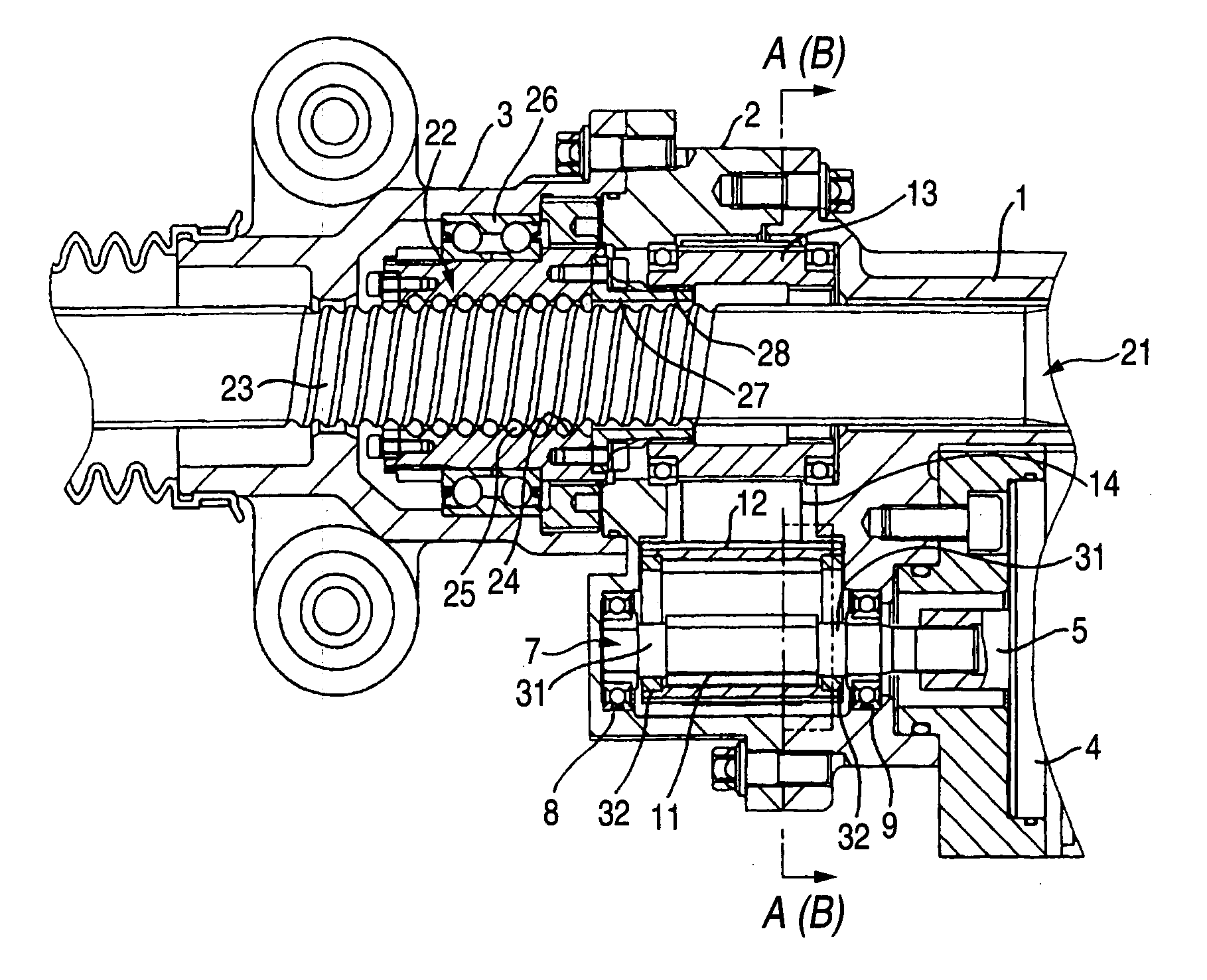
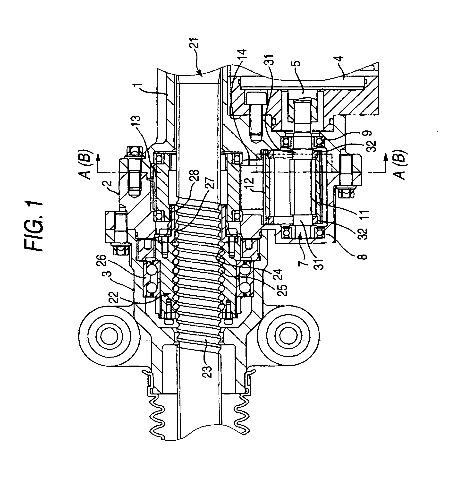
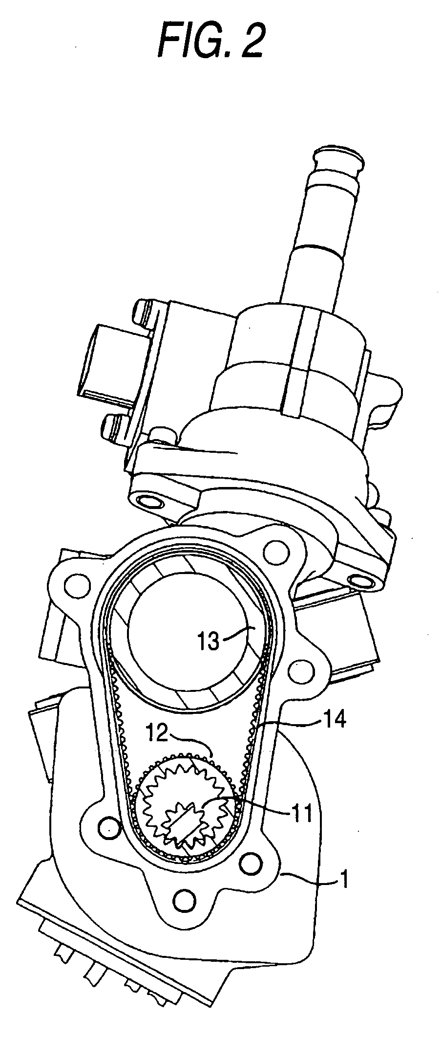
[0140] When the drive shaft 5 of the electric motor 4 is rotated, the external gear 11 is rotated, and its rotation is transmitted to the internal-external gear 12 and further transmitted to the driven side pulley 13 via the belt 14.

[0141] At this time, the belt 14 is to be moved in the axial direction by a direction and inclination of the core wire of the belt and by a twist of the belt 14 itself.

[0142] The internal-external gear 12 is also to be moved in the axial ...

third embodiment

[0149]FIG. 7 is an enlarged sectional view showing a primary portion of a ball screw type different shaft type rack-assisting type electric power steering apparatus of the third embodiment of the present invention.

[0150] A basic structure of this embodiment is the same as that of the embodiment described above. Only different points will be explained below.

[0151] In this embodiment, the circular support body 31 and the annular support body 32 respectively include a movement regulating mechanism for regulating a movement of the internal-external gear 12 in the axial direction.

[0152] As shown in FIG. 7, the movement regulating mechanism is composed in such a manner that the contact portions of the circular support body 31 and the annular support body 32 are tapered shaped, opposed to each other and symmetrically to each other.

[0153] In this embodiment, when the internal-external gear 12 is to be moved in the axial direction by torque given from the belt 14, in this embodiment, the...

fourth embodiment

[0158]FIG. 8 is a longitudinal sectional view showing a ball screw type different shaft type rack-assisting type electric power steering apparatus of the fourth embodiment of the present invention.

[0159] A basic structure of this embodiment is the same as that of the embodiment described above. Only different points will be explained below.

[0160] In this embodiment, an oblique tooth belt 41, on the inside of which engagement teeth are formed, is provided between the engagement teeth on the outer circumferential face of the internal-external gear 12 and the engagement teeth on the outer circumferential face of the driven side pulley 13 arranged on the same axis as the rack shaft 21 described later.

[0161] When a rotation of the internal-external gear 12 is transmitted to the driven side pulley 13 via the oblique tooth belt 41, the oblique tooth belt 41 is to be moved in the axial direction by the angle of the oblique tooth, the direction and inclination of the core wire and the twi...


PUM


Abstract

In an electric power steering apparatus, in which an auxiliary steering torque is generated by an electric motor according a steering torque impressed upon a steering wheel transmitted to a rack shaft of a steering mechanism via a power transmission mechanism. The power transmission mechanism has a small diameter external gear, and an outer circumferential face thereof acts as a drive side pulley, a driven side pulley driven by the internal-external gear and a ball screw mechanism driven by the driven side pulley so as to move the rack shaft. A circular support body is concentrically provided at the external gear and an annular support body, which supports the circular support body, is concentrically provided at the internal-external gear so as to be inscribed with the circular support body.

Description

TECHNICAL FIELD [0001] The present invention relates to a ball screw type different shaft type rack-assisting type electric power steering apparatus. BACKGROUND ART [0002] In a field of a power steering system incorporated into a vehicle, a so-called power steering system, in which steering operation is assisted by an external power source, is widely used. It is conventional to use a vane type hydraulic pump for the power source of the power steering apparatus. In many cases, this hydraulic pump is driven by an engine mounted on the vehicle. However, in this type power steering apparatus, since the hydraulic pump is driven by the engine at all times, loss of power in the engine becomes large (when a maximum load is given to the hydraulic pump, the loss of power is several horsepower or 10 horse power). Therefore, it is difficult to apply this type power steering apparatus to a light car, of which engine displacement is small. Also, even when this type power steering apparatus is app...

Claims


Application Information

Patent Timeline
Patent Type & Authority Applications(United States)
IPC IPC(8): B62D5/04
CPCB62D5/0424F16H55/171F16H7/023B62D5/0448
Inventor MIZUTANI, HIROTOTATEWAKI, OSAMU
Owner NSK LTD
Why Eureka
Try Eureka